There are situations in which it may be necessary to tweak friction coefficient in a nonlinear contact analysis during the simulation. Currently, the Ansys Workbench GUI does not support this capability directly; however, it is possible to vary the friction coefficient using a command object.
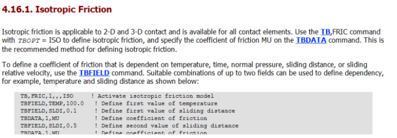
The Ansys documentation has several references of doing this as listed under the Help section; Mechanical APDL > Material Reference > Nonlinear Material Properties > Contact Friction as shown below.

This section on the documentation describes defining contact friction using TB,FRIC which is a material property used with current technology contact elements. It can be used to define coefficient of friction for both isotropic or orthotropic friction models. It further discusses varying friction coefficient in a multiple load step scenario, as well as implementing user defined friction using TB,FRIC with TBOPT = USER.
The example presented here will show how to use commands object within Workbench to vary friction coefficient. The friction coefficient is defined via the TB,FRIC command. To define the friction that is function of temperature, time, normal pressure, sliding distance, etc. you can use the TBFIELD command in conjunction with the TB,FRIC. In this example presented, the friction is varied with time (to simulate it’s change through the load step).
Below is a graphic of the nonlinear contact between the Aluminum housing and steel ring gear.

The command object used to modify friction as a function of time is shown below.

This command object uses the information in the table below to modify friction :
Time Friction Coefficient
0 0
0.2 0.1
0.4 0.3
0.6 0
0.8 0.15
1 0
As an example of the friction can vary, notice the friction coefficient is zero for time = 0.6 and time = 1.0.
During the run, the output controls under Analysis Settings was set to Yes for Nodal Forces, Contact Miscellaneous and General Miscellaneous.
A quick look at the contact results confirms our findings. The contour plot for contact friction stress shows zero results for time = 0.6 and 1 which m

Another sanity check is to check for reaction force through the frictional contact with the extraction method set to contact element option; this also reveals zero (nearly zero reaction force at these time points). The very small discrepancy noted on the reaction force is due to a few overlapping nodes on a boundary condition.

