Bucket conveyor models in Ansys Rocky use somewhat complex motion definitions to define the motion up the grain leg, around the head pulley, down the grain leg, and finally around the tail pulley. It is common to know the RPM of the driven pulley, so defining the motion based on this parameter is very convenient. In this post, we will demonstrate the use of expressions in Ansys Rocky to do just that.
When setting up a bucket elevator simulation, import only a single bucket. The bucket’s mounting location should be even with the center of the tail pulley. The geometry will be replicated using the “Replicate Geometry” feature.

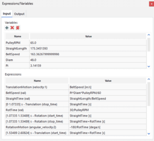
Next, insert a motion frame, connect the motion frame to the bucket geometry, and via the tools menu enable Expressions/Variables. The image below details the initial position of the bucket geometry and the relevant motions that must be defined. Note that based on the initial position of the bucket, there will need to be four sequential motions defined for the motion frame. These are Translation 1, Rotation 1, Translation 2, and finally Rotation 2.

These motions will be defined based on start and stop times for a given motion as well as the relevant velocity. This leads to the relevance of expressions to define the time required to perform each motion as well as the velocity based on the relevant known parameters. It is important to also note that the motion frame does not need to be in contact with the object that it is tied to. In this case it is beneficial to locate the motion frame at the center of the tail pulley. This location will make it easier to define the rotation motions.
Take the first translation as an example. The motion will start at t=0 and the bucket must traverse the distance equivalent to the center to center distance between the two pulleys, which is known to be 182.6 inches. Using the known head pulley diameter and rotational speed of 65 RPM, the linear velocity of the belt can be determined using Pi * Diam * PulleyRPM/60 as shown below.
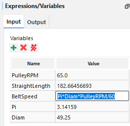
The other required input for Translation 1 is to compute the length of time it will take the bucket to traverse the first straight section of belt. This can be computed via dividing the straight length of belt by the belt speed as shown below.
![]()
To setup Translation 1 in the motion frame, add a translation motion with a “Stop Time” equal to “StraightTime” and a velocity of “BeltSpeed” in the appropriate direction.
![]()
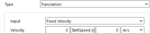
Note that it is important to add units to these inputs. [s] for StraightTime and [in/s] for BeltSpeed.
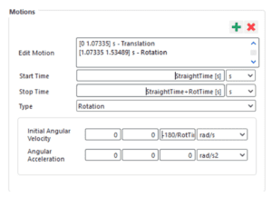
The next motion will require a few additional expressions. First, we will define the time to complete a semicircular rotation around the head pulley. Knowing the RPM of the pulley and that the desired motion is half of a revolution, the formula to compute the time of half a rotation simplifies to RotTime = 30/PulleyRPM. Finally, we need to determine the angular velocity. This can be computed as AngVel = -180/RotTime [dega/s]. This can be entered directly into the motions panel, or can be added as an additional Variable.
The Start and Stop Times can be defined using the StraightTime and RotTime variables already defined. The Start Time for this motion is after the end of the initial translation, therefore the start time is equal to “StraightTime.” The Stop Time is the duration of the translation and the impending rotation, so is equivalent to “StraightTime+RotTime.” The Initial Angular Velocity field is filled using the angular velocity calculation noted above.
The remaining translation and rotation motions can be defined using the same approach.
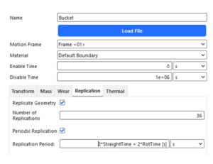
Following the remaining motion setup, the final step is to include replication of the bucket geometry. Navigating to the bucket geometry, set the Motion Frame to the frame just created and proceed to the Replication tab. Enter the number of buckets you will need and enter the replication period. The replication period is the length of time needed to complete one full loop around the conveyor. In this case it is equivalent to “2*StraightTime + 2*RotTime.”
Note that the Expressions section of the Expressions/Variables panel is a list of where expressions or variables have been used in the model.
While this article explains the setup of a bucket elevator, expressions are quite valuable for other Rocky simulations as well. When calculation is needed to convert between a key value and the inputs needed to implement that change in Rocky, expressions and aid in accuracy and speed of running multiple test cases. For this example, it is trivial to run the model at different head pulley speeds as only the PulleyRPM variable needs to be modified.
Check out our website for other tips, tricks, and Ansys content.