How Subtle Nozzle Modifications Make a Big Impact

Introduction

In many automotive and industrial applications, the performance of liquid spray nozzles can significantly affect efficiency, lubrication, combustion, or cooling. Despite their importance, engineers often rely on assumptions or trial-and-error testing, which can lead to sub-optimal results. For applications where liquid behavior is difficult to characterize, having accurate models is essential for making informed design decisions.

Anticipating how spray patterns change with minor geometric modifications can reduce uncertainty in the design process. This brief study demonstrates one approach to using CFD for rapid nozzle prototyping.

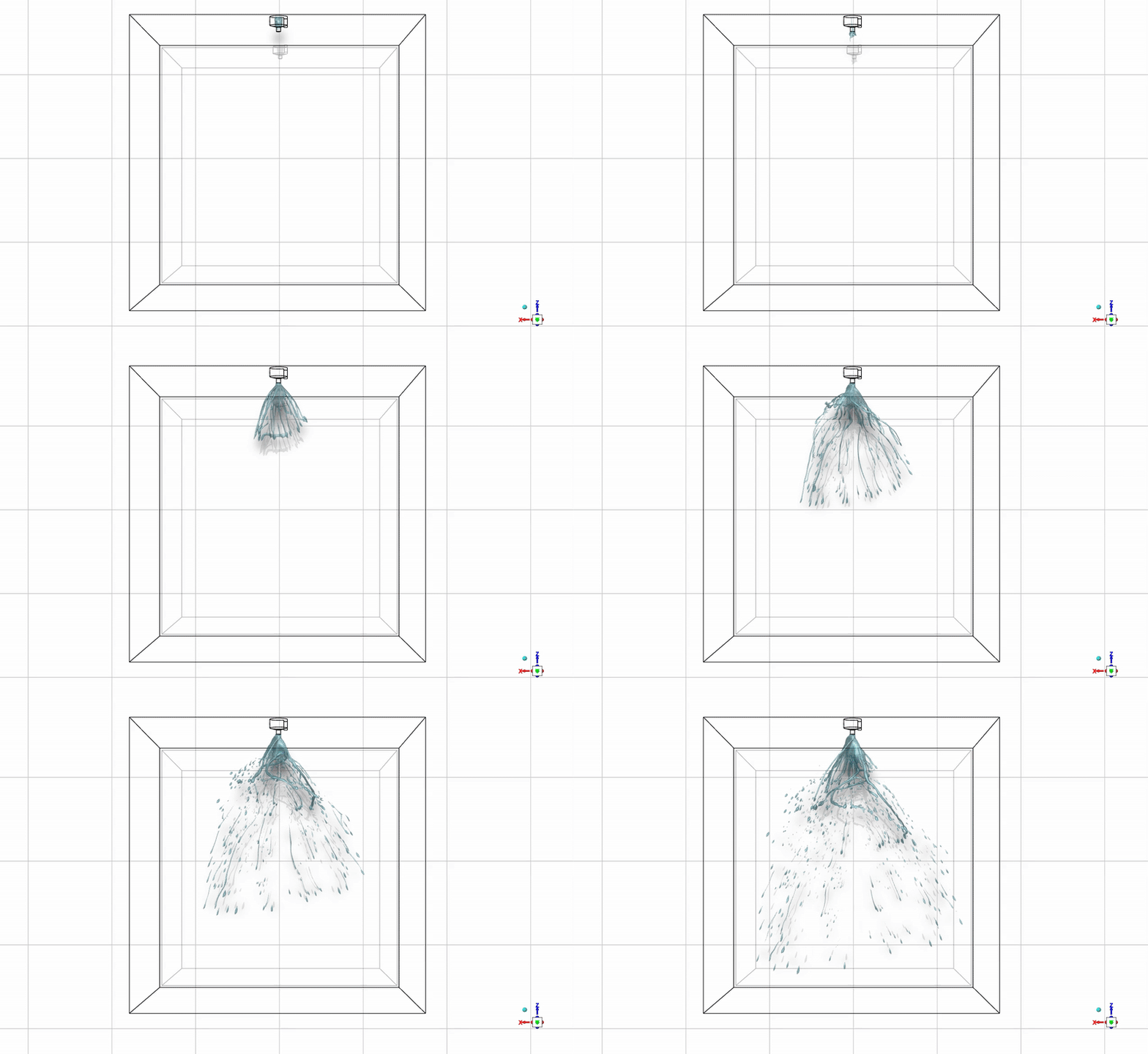
To showcase the capabilities of Ansys Fluent in modeling liquid sprays across various applications, a simple case study is presented. Both cases use the Volume of Fluid (VOF) model, as shown in the animation below, with identical solver settings to isolate the effect of nozzle geometry.

Could a small geometric change to the nozzle lead to more optimal spray distribution?

To find out, we used Ansys Fluent’s Volume of Fluid (VOF) model to simulate and compare the spray characteristics of two nozzle designs under identical operating conditions in our recent webinar.
Comparing Two Nozzle Geometries Under Identical Conditions

The two nozzle designs depicted below are used for this evaluation.

Case 1: Straight Nozzle Design

This design features a cylindrical outlet with sharp edges. The geometry allows the fluid to exit the nozzle along a more direct path, resulting in a relatively narrow spray pattern in the simulation.

Case 2: Rounded Nozzle Design

This version includes a smoother, rounded transition from the internal chamber to the nozzle throat. The modified geometry changes the way the fluid exits, producing a noticeably wider and more dispersed spray.

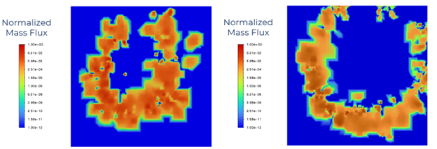
Both cases were simulated using the same transient setup over a 0.25-second interval, with all solver parameters held constant to isolate the influence of geometry alone. Within the simulation domain’s bounding box, normalized mass flux results are displayed at both the midplane and bottom surfaces for comparison, as shown below.
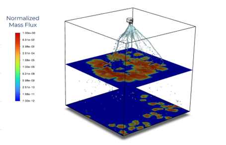
While this comparison focuses on qualitative differences in spray coverage, the same simulation method can be extended to evaluate more complex fluid interactions with CAD geometries. By extracting variables such as heat transfer coefficients, surface wetting behavior, or localized flow rates, this approach supports performance analysis across a wide range of engineering scenarios. When the final nozzle design or arrangement of multiple nozzles is not directly visible (E.g. oil nozzles within an engine or gearbox), simulations can offer critical insights into the impact of design decisions.

Midplane contours of the mass flux for both cases are shown and discussed in the following section.
Observations and Design Implications

  • Straight Outlet (Case 1): Suitable for applications requiring a more focused spray pattern, such as targeted lubrication or fuel delivery.
  • Rounded Outlet (Case 2): Better suited for applications that benefit from broader coverage, such as cooling, surface treatment, or agricultural spraying.
  • Design Insights: Even small geometric changes, such as rounding a sharp edge, can significantly influence spray distribution. CFD modeling offers a practical method for evaluating these effects during early design phases. Asymmetric spray patterns are observed in both cases, which may result from the asymmetric inlet or provide insight into transient start-up behavior in these nozzle designs.

To summarize, these simulations illustrate how subtle geometric changes can be evaluated during early design phases to inform engineering decisions, especially when physical prototyping and testing are time-consuming, impractical, or costly.

See the Simulation in Action

To explore these results in more detail, including how the spray evolves over time and interacts with surrounding geometry, check out the full simulation walkthrough in our recent webinar with Dr. Ted Sperry. He’ll also cover tips for modeling pressure swirl atomizers and other complex spray systems in Ansys Fluent.

Why is Ansys Rocky a Must-Have for Engineers?

Introduction

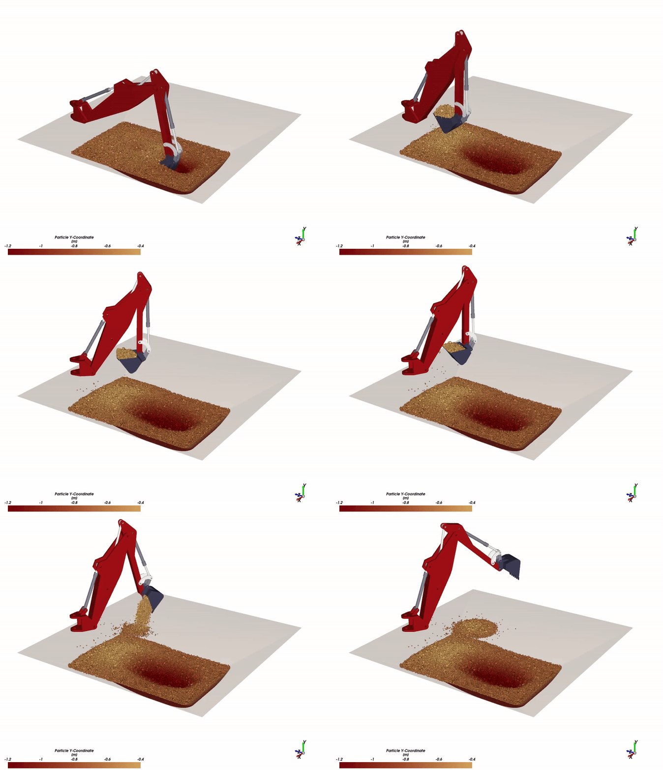
In the fast-paced world of engineering simulations, Ansys Rocky stands out as a game-changer for particle dynamics. Whether you’re working in mining, pharmaceuticals, agriculture, or any industry that deals with bulk materials, Ansys Rocky provides unmatched accuracy, speed, and scalability in Discrete Element Method (DEM) simulations.

As industries push the boundaries of digital engineering, integrating Ansys Rocky with CFD (Computational Fluid Dynamics), FEA (Finite Element Analysis), and Multiphysics solutions ensures a comprehensive approach to real-world problem-solving. In this blog, we’ll explore how Ansys Rocky is reshaping engineering design and how you can leverage it for optimized results.

What Makes Ansys Rocky Stand Out?

1. Advanced Particle Shapes and Breakage Modeling

Unlike traditional DEM tools that rely on spherical approximations, Ansys Rocky allows for realistic particle shapes, including clusters, fibers, and shells. This results in highly accurate predictions of bulk material behavior, leading to more reliable product designs and operational insights.

2. Seamless Multiphysics Integration

By integrating with Ansys Fluent and Ansys Mechanical, Ansys Rocky enables users to study:

  • Fluid-particle interactions (ideal for industries like pharmaceuticals and food processing)
  • Structural loads due to bulk materials (important in conveyor and mining applications)
  • Thermal effects on particle flow This synergy provides engineers with a holistic understanding of how materials behave under various conditions.

3. GPU Acceleration for Faster Simulations

Time is money, and Ansys Rocky ensures maximum efficiency with its GPU-accelerated solver. Users experience up to 50x faster computation speeds compared to traditional CPU-based solvers, significantly reducing simulation time and enabling rapid design iterations.

4. Realistic Conveyor and Comminution Analysis

For industries dealing with bulk material transport, Ansys Rocky provides detailed conveyor belt wear analysis and crusher/grinder efficiency predictions. These insights help manufacturers optimize equipment lifespan, reduce downtime, and improve overall productivity.

Our exclusive webinar will walk through real-world case studies, demonstrate simulation workflows, and show how Rocky integrates with other Ansys tools effectively. 

Industry Applications

1. Mining and Material Handling

  • Predict and mitigate conveyor belt wear and tear
  • Optimize grinding and crushing efficiency
  • Reduce maintenance costs and improve operational reliability

2. Pharmaceuticals and Food Processing

  • Model tablet coating and powder mixing
  • Improve granulation and capsule filling processes
  • Enhance product uniformity and reduce waste

3. Agriculture and Fertilizer Production

  • Simulate grain flow and storage behavior
  • Optimize fertilizer blending and application processes
  • Reduce handling losses and ensure product consistence

How to Get Started with Ansys Rocky

Step 1: Define Your Simulation Objectives

Identify what you want to achieve—whether it’s reducing equipment wear, optimizing material flow, or improving product consistency.

Step 2: Import and Set Up Geometry

Ansys Rocky allows direct CAD imports, making it easy to create accurate simulations with real-world geometries.

Step 3: Select the Right Particle Model

Choose from a variety of particle shapes and material properties to best represent your system.

Step 4: Run GPU-Accelerated Simulations

Leverage parallel processing for faster and more detailed results.

Step 5: Analyze and Optimize

Use Ansys Rocky’s visualization tools to interpret results and refine designs for maximum efficiency.

Conclusion: Why Ansys Rocky is a Must-Have for Engineers

Ansys Rocky is more than just a DEM tool—it’s a simulation powerhouse that bridges the gap between physics-based modeling and real-world applications. With advanced particle modeling, seamless multiphysics integration, and high-speed processing, it is a must-have solution for industries looking to innovate and optimize their bulk material handling processes.

If you’re ready to take your simulations to the next level, contact us today for a demo or trial of Ansys Rocky and see how it can transform your engineering workflow! Our upcoming webinar showcases the advanced simulation tool designed for modeling granular and discontinuous materials across industries like pharmaceuticals, mining, food processing, and manufacturing.