Let’s continue our discussion on fracture mechanics with this second blog post, where I dive into the methods engineers have available to evaluate cracked structures. If you’ve missed part 1 of this blog series, go back and read it here.
Stationary, Static and Fatigue Cracks
When evaluating a structure with cracks, engineers have a few options with respect to the level of involvement in solving the problem. From least to most involved:
- Stationary: review of status of crack, ignoring crack growth.
- Static: review of status of crack under single, monotonically increasing load, crack growth is assumed.
- Fatigue: review of status of crack under cyclic loading, crack growth is assumed.
Stationary cracks provide an instantaneous view of the state of a crack in the structure. The engineer can only know one thing from this type of analysis: will the crack grow or not. No insight is provided into the second and third of the common questions asked in the previous section. Simple closed-form solutions are available for engineers to estimate the integrity of a cracked structure, and these can be found in literature reviews and textbooks. Many closed-form solutions take the resulting stress field caused by loading, the current crack length, and an empirically determined factor to determine stress intensity. A few examples are shown here, for plate geometry of varying sizes.

Image Source: Elementary Engineering Fracture Mechanics, 4th Ed., Broek, pg. 85
Static cracks allow the engineer to determine if a crack will grow and fast fracture, or if the crack will arrest. Static cracks are subjected to a single, increasing load, from unloaded to fully loaded. In this case, we are not interested in a time frame for the crack to grow or arrest; ultimately, engineers simply determine if the structure will break with the presence of the crack.
Fatigue cracks, or fatigue crack growth, is the most complex case, both for understanding and to consider when designing a product. Fatigue crack growth considers the structure under cyclic loading, where the structure is repeatedly loaded and unloaded. There are variations to this load pattern as well, which we will not go into here.
When it comes to fatigue cracks, there are additional test procedures to determine a crack growth rate versus the applied stress intensity. Engineers will typically see this abbreviated as da/dN vs. dK, i.e., the change in crack extension (da) over cycles per extension (dN) vs. change in stress intensity (dK). Like critical fracture toughness, every material will have a different crack growth curve. Examples of some different material curves are shown here.

The unique aspect of fatigue crack growth that harkens back to what Griffith found is the stress levels in the structure can be much less than those that would normally cause plastic collapse. Cyclically loading the structure will continue to grow the crack, under no threat of plastic collapse, and when the maximum stress intensity factor is less than the critical fracture toughness; we call this subcritical crack growth.
Most crack growth data focus on this subcritical crack region, however, two other regions exist. Let’s limit the data shown in the previous graph to one material’s data set and expand the representative data out; we get a graph that looks like this.

The material data mentioned fits into the area marked ‘Region II’; on a log-log plot of crack growth rate versus change in stress intensity, this is commonly referred to as the Paris regime, and it is generally a straight line on this plot. A simple equation is used to describe this region, which takes the form of:
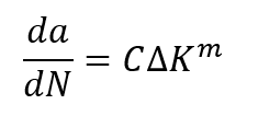
where C and m are material constants determined via the graphed data. The other two regions, I and III, refer to the threshold and fast fracture regions, respectively. The threshold region describes when the crack grows slowly, either by small stress intensity or small crack size. Conversely, the fast fracture region describes rapid crack growth, which may result in surprise failure of the structure. Engineers use this crack growth data in damage tolerance assessment.
In both the first and second blog posts, I’ve not touched on Ansys simulation to solve fracture mechanics problems. In the next blog post, I will discuss Ansys’ capability to model cracks and solve crack growth problems.