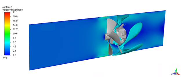
When setting up rotating machinery in Fluent, users will specify a rotating cell zone with the appropriate angular velocity. The bounds of this domain must be surfaces of revolution for either the frame motion or sliding mesh approaches. This article focuses on the finer details of setting up such a case. Particularly, what needs to be done for walls on the boundary of a rotating zone that should not be rotating? Additionally, sometimes a rotating shaft will exist both within a rotating zone and also within an adjacent stationary zone, how should this be handled? This article will answer these questions.
As an example, consider a case where a fan is placed within a circular duct. It is held in place via the motor and motor mounts. The domain will be split into rotating and stationary zones about halfway along the shaft that connects the fan and motor assembly.
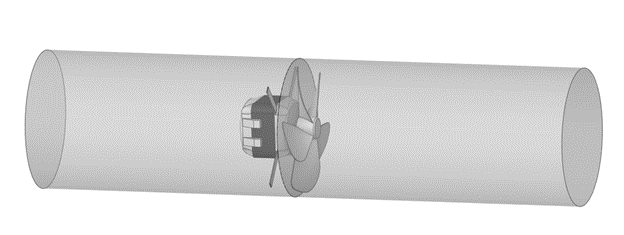
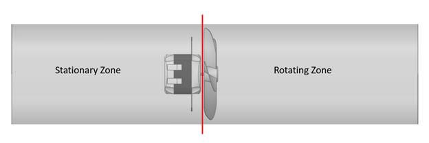
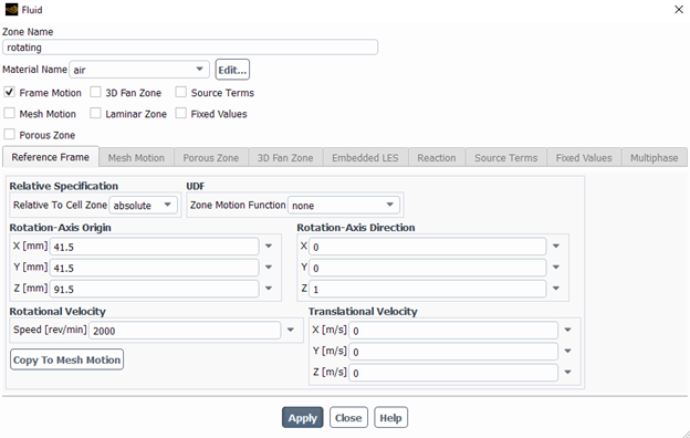
The setup of the rotating zone itself is straightforward. For this analysis, the frame motion approach will be used. In the Cell Zone Conditions Panel, the “Frame Motion” box will be checked and the appropriate rotation axis, rotation axis direction, and rotational velocity will be set.
In Fluent, all walls are stationary relative to their adjacent cell zone. This means walls within or on a rotating zone are rotating with that zone. Similarly all walls within or on a stationary zone are stationary. Consider the two images below. The duct in the rotating cell zone should not be rotating with the fan. Conversely, the motor shaft that extends into the stationary zone should be rotating, while the cell zone should be stationary. These conditions need to be applied at the boundary level for these two walls.

To address the duct, the user needs to edit the appropriate wall boundary condition. It is helpful to identify where walls will need specific boundary condition settings in the geometry phase so that appropriate named selections can be added to the boundaries. In the boundary condition edit panel, wall motion will be set to “Moving Wall” in the “Absolute” frame. The axis will be setup appropriately with a speed (angular velocity) of zero. Keep in mind that we are defining a wall that will be stationary in the global frame. It can be confusing to select the moving wall option here, but take note of the default option. By default this wall was “stationary” relative to the rotating cell zone, hence the need for this change.
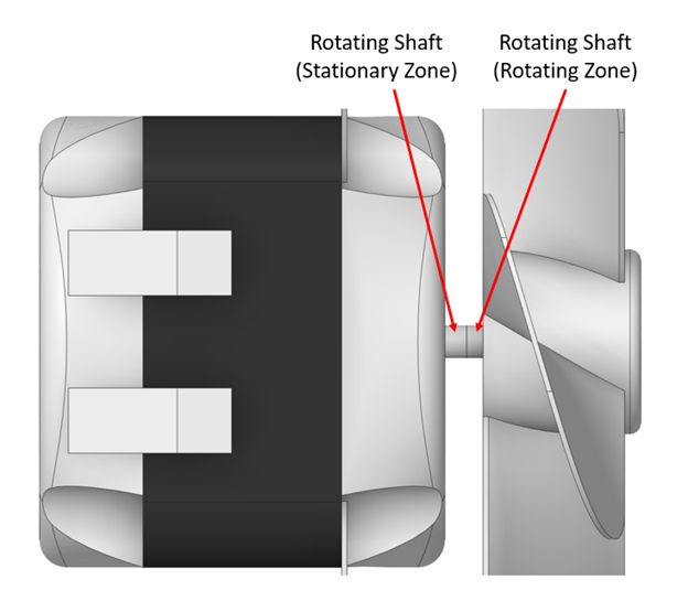
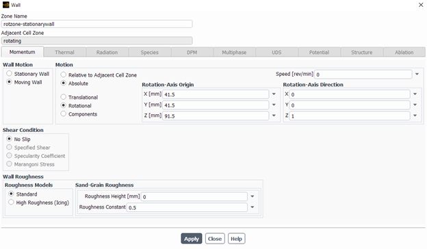
The small section of shaft in the stationary zone will be treated similarly, but will instead have the same angular velocity as the rotating zone. In this model the small section of shaft in the stationary zone likely does not change the result much, but this will not always be the case.
One very important aspect of applying wall velocities as done for both the duct and the shaft is that no velocity can be applied normal to the wall. In the case of cylindrical walls, only rotational velocity around the axis of the cylinder is allowed.
