A common technique in distributing ducted flow involves thin guiding vanes or baffles. One of the biggest hurdles to modeling baffles is how thin they are relative to the rest of the model. If you were to model their true thickness, you typically have a choice between poor quality skewed elements or an excessively high mesh count. Instead, thin baffles are often approximated as infinitely thin.
When using Fluent Meshing, the addition of surface bodies in SpaceClaim to represent each baffle is perhaps the quickest approach to adding in baffle geometry. In some cases it is also possible to split up the fluid volume to account for these baffles, but generation of non-manifold geometry is not a viable approach, so this is typically more challenging than the surface body approach.
It is also important to consider inflation on zero thickness baffles. If one was to resolve the actual thickness of a baffle, inflation could wrap around the baffle without issue, but this is not the case for a zero thickness baffle. Instead, inflation will be forced to stair-step wherever the baffle ends in the middle of the fluid volume. These stair-stepped elements are of poor quality and will negatively affect the convergence behavior of the solution.

To prevent stair-stepping, inflation must be allowed to wrap fully around an object, or extend to an external boundary. To accomplish this for the case of zero thickness baffles, additional surfaces must be added to the geometry. Inflation layers can be grown on surfaces that allow flow to pass through them. It would be typical to consider these as “meshing surfaces” as their only purpose in the model is to aid in mesh quality by preventing stair-stepping of inflation layers.
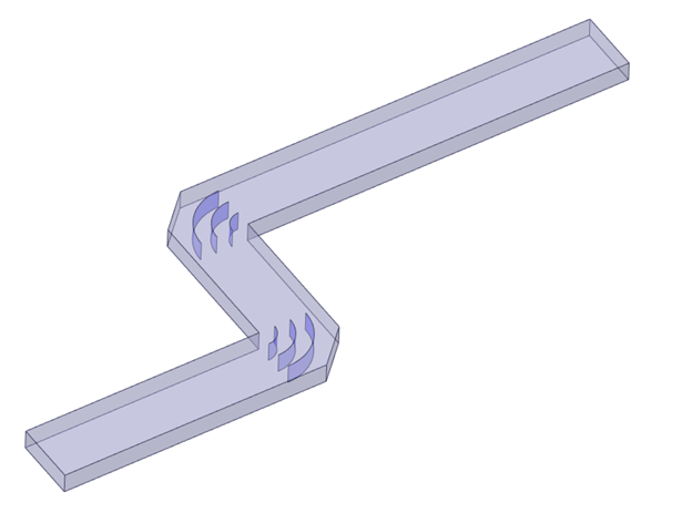
In the case of turning vanes in a duct as pictured in this article, it makes sense to create extensions to the turning vanes that terminate at the inlet and outlet. Note that these additional surfaces must be separate faces from the actual vanes themselves. This is so that the meshing surfaces can be set to interior type boundaries in the solver. This will allow flow to pass through the meshing surfaces unobstructed.


To achieve continuous inflation using these new meshing surfaces, there are two approaches in Fluent Meshing. First, you can intentionally set the meshing surfaces to the wall boundary type in the Update Boundaries task. This will allow you to grow inflation using the default Add Boundary Layers control. When choosing this option it is important to set the meshing surfaces to “Interior” type boundaries once inside the solver otherwise flow will not be able to pass through these surfaces. The second option while meshing is to set the meshing surfaces to “internal” boundaries in the Update Boundaries task. This will then require that you manually scope your boundary layers for these surfaces, but avoids the need to change the boundary type later in the solver. Note that the terminology for a conformal boundary that allows flow to pass through it is different for the mesher and the solver. In the mesher this is “internal” and in the solver this is “Interior.”
Regardless of approach, the final mesh should have no stair-stepping of inflation as shown below.

If in your final model you have no need for multiple cell zones, then you can merge the multiple cell zones together inside of the solver. To do so, go to the Domain Tab > Combine > Merge and select the relevant cell zones. This will remove the workflow information from the case file, so be sure that you have saved the .msh.h5 file separately before performing this operation.