Ansys Mechanical Fracture Mechanics
Ansys Mechanical Fracture Mechanics
one-day courseFracture mechanics allows engineers to analyze the integrity of a structural component, where traditional methods of stress analysis are not applicable. Cracks are sharp corners, and traditional finite element analysis does not provide accurate stress at a sharp corner, also known as a singularity. The primary questions engineers are trying to answer when performing a fracture analysis are:
-
Will a crack grow under these loading conditions?
-
Where will the crack grow?
-
How long will it take for a crack to grow until the part breaks?
This 1-day course will give attendees experience in setting up, solving and post-processing finite element models with cracks in structural components. Information, such as Stress Intensity Factors, SMART (Separating, Morphing and Adaptive Remeshing Technology) crack growth and techniques for creating cracks in the finite element model will be covered.
Prerequisites for this course are DRD’s Introduction to SpaceClaim for Mechanical and Introduction to Ansys Mechanical courses. DRD recommends that students who do not have these prerequisites delay attending the course until they attain them. This is a challenging course for proficient users.
Chapter 1 – An Overview of Fracture Mechanics in Ansys
Workshop 1: Ansys Stress Intensity Factor Solution with a Simple Edge Crack Model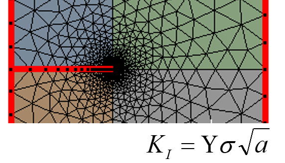
The objective of this workshop is to provide a simple basis for modeling cracks in Ansys Mechanical. The students start with a 2D plate structure and create an edge crack with the Pre-Meshed Crack capability. The student will then post-process fracture parameters, such as Stress Intensity Factor (SIF), and compare the output with a closed form solution found in many elementary fracture mechanics’ text.
The student is also introduced to residual strength curves, from both the fracture failure mode and the limit load failure mode. These curves help determine the first mode of failure for the structure.
Workshop 2: Calculation of Stress Intensity Factor at an Elliptical Crack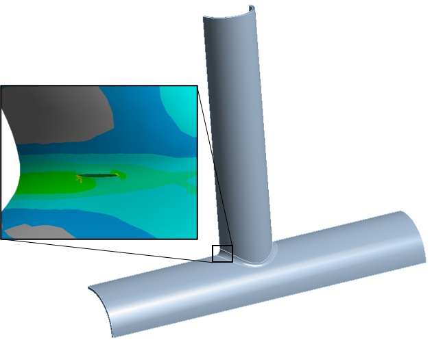
This workshop expands on the basic setup and output of the previous workshop, into a 3D model. Here, a welded pipe joint is subjected to pressure with a crack on the exterior of the pipe wall. The student will learn how to create an elliptical (or penny)-shaped crack without any prior geometry modification.
3D contours of Stress Intensity Factor are calculated for the initial case of crack size. Then, the student will modify the crack size definition, rerun the model, and compare the two solutions.
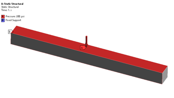
Workshop 3: Edge Cracked Plate VCCT Fracture Mechanics with Closed Form Solution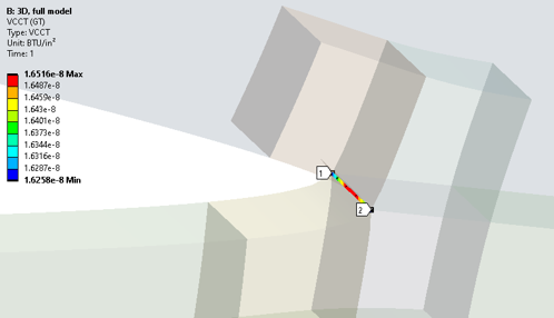
Like workshop 1, the objective of this workshop is to setup and solve a simple 3D edge cracked plate model under modeI loading. In this instance, the student will use the Virtual Crack Closure Technique. Also known as MCCI (Modified Crack Closure Integral), this method calculates a Strain Energy Release Rate (SERR) for the fracture parameter.
Students will then compare this with a closed form solution, as well as experiment with calculating a Stress Intensity Factor using Irwin’s equation.
Workshop 4: Calculation of Stress Intensity Factor and Energy Release Rate for a Double Cantilever Beam
Workshop 5: ANSYS VCCT Solution of a 4-Point Bend Test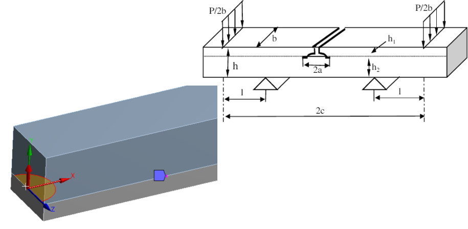
Workshops 4 and 5 demonstrate other cases of setting up and solving simple stationary crack models in Ansys Mechanical. Workshop 4 has the student setup a double cantilever beam structure. Workshop 5 uses a 4-point bend structure. Both cases have simple closed form solutions to compare to that allow validation of Ansys fracture results with known solutions.
Chapter 2 – Model Crack Growth in Ansys
Workshop 6: Computing Crack Growth with ANSYS SIFs and the Paris Law on a 2D Pressure Vessel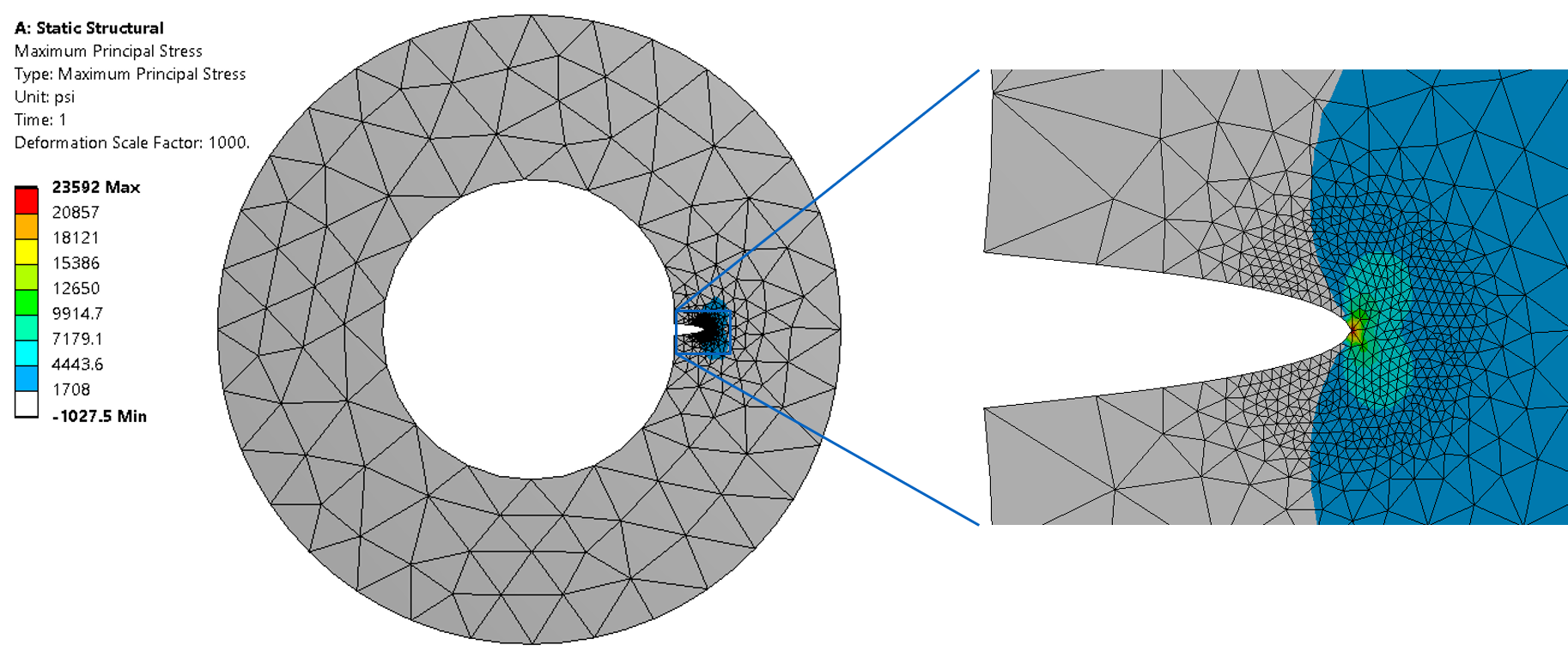
The objective of this workshop is to provide the groundwork for crack growth analysis. In this workshop, students solve a 2D pressure vessel study for varying crack lengths using Ansys Mechanical with a parametric model.
The workshop then provides a basis for computing crack growth information using a spreadsheet, allows the student to experiment with the crack growth computation, and asks several engineering questions:
· What crack length causes immediate fracture?
· Is limit load exceeded?
· Is the curve fit for crack growth adequate for small cracks?
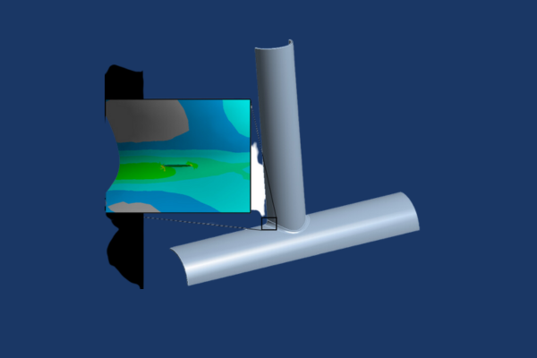
Workshop 7: SMART Crack Growth on Intersecting Pipes
This workshop is the first of two workshops that demonstrate the use of SMART. Students will learn how to setup an automated crack growth analysis using the Semi-Elliptical Crack combined with SMART Crack Growth object. Detailed definition of the Paris Law material constants for crack growth is also covered.
Automated crack growth has a host of new results post-processing options for Crack Extension, Equivalent Stress Intensity Range and Cycles; students will work through these options as well.
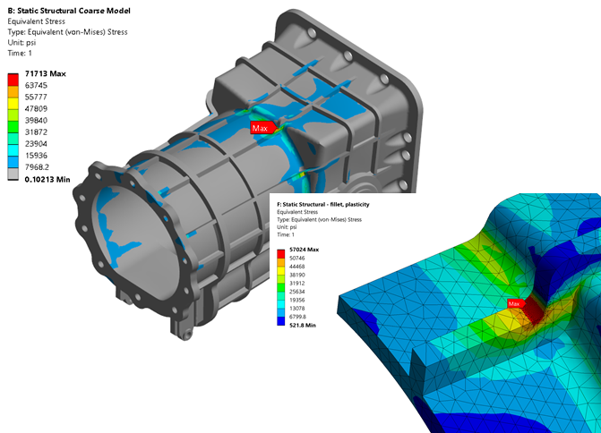
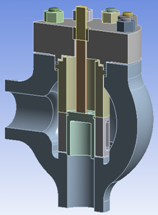
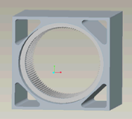
Workshop 8: SMART Crack Growth on a Casting with a Thermal Gradient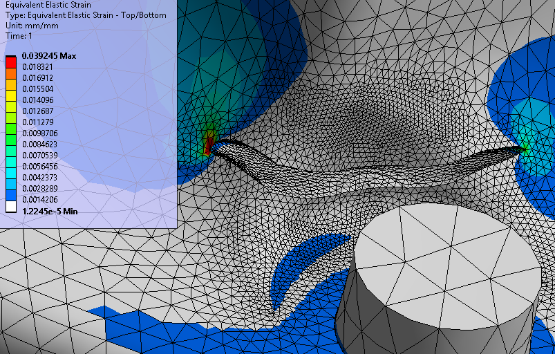
In this workshop, students learn how to create a crack using a 3D surface representation of the crack surface. This is made possible via the Arbitrary Crack feature, which allows a complex, non-planar 3D surface to be used as a basis for generating a crack mesh.
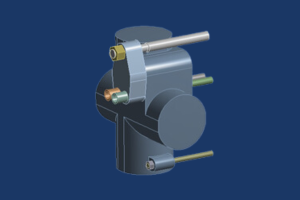
Workshop 9: SMART Crack Growth on a Casting with an Initial Stress State
This workshop is a continuation of workshop 8, where students load a casting with a thermal gradient and grow a crack. In this workshop, an initial stress state is set up that includes this thermal gradient and bolt pretension. The initial stress state is passed to a downstream analysis where the cyclic load to grow the crack is pressure. SMART crack growth is used here; Ansys automatically handles this initial stress state each time the crack calculation is performed.
Chapter 3 – Modeling Adhesive Failure
Workshop 10: Adhesive Failure Modeling with Contact Debonding
This workshop demonstrates modeling failure of an adhesive layer via bonded contact. Students define a cohesive zone material model with properties for maximum normal stress and critical fracture energy. The benefit of this capability is that the adhesive layer does not need to be directly modeled. This is a huge benefit as the adhesive layer is typically much smaller in thickness compared to the parent parts bonded together. A secondary benefit is the mesh does not need to be the same on either side of the interface, as contact is used to initial tie the parent parts together.
Workshop 11: Adhesive Failure Modeling with Interface Delamination
This workshop demonstrates a second method to simulate interface failure; interface delamination. A similar material model is defined for this method. However, contact is not required for this capability. Instead, the mesh on both parent parts must be the same at the interface with the adhesive. This is accomplished through clever meshing or match mesh controls. The interface delamination capability also has another special use case: delamination modeling with composite models created in Ansys Composite PrepPost.


 1940 earthquake of El Centro, CA. The student solves the model using the ground motion acceleration time history in a mode superposition transient analysis and then solve the same model using the corresponding response spectrum.


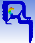
 to be plastically deformed into the seal, which is a hyperelastic body. A pressure is applied to the inside of the tube at a subsequent time. The o-ring undergoes severe deformation; the Nonlinear Adaptive Remeshing technique is used to remesh the model during the solve process automatically to get a completed solution, rather than the user remeshing manually if the model fails to solve.