Understanding stress vs. strain is fundamental for engineers working with material properties. However, a critical distinction exists between the stress-strain data obtained during tensile tests and the true stress-strain data required for accurate simulations in software like Ansys Mechanical.
In this article, we’ll uncover the essential differences, explain how to calculate true stress and strain, and explore why these concepts are indispensable for accurate elastic-plastic material simulations.
What is Measured and Calculated During Material Tensile Testing?
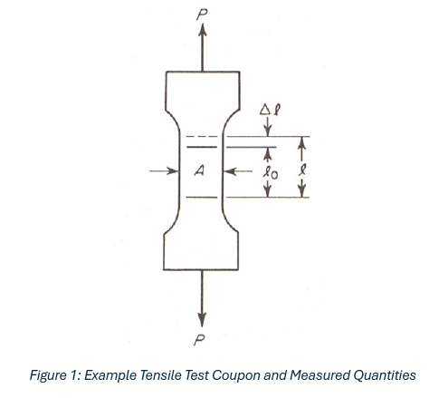
If you were to internet search for a material’s stress vs. strain data or look in the back of an engineering mechanics textbook, the stress vs. strain data provided is typically in the form of engineering stress and strain. Tensile testing for stress vs. strain is performed using tensile coupons like the layout shown in Figure 1.

This layout includes data that is measured as part of the test, where:
- P = the applied load
- A = the initial cross-section area
- l0 = the initial extensometer length
- l = the new extensometer length after applying load P
The calculated stress and strain are:
σengineering = P / A
εengineering = (l – l0) / l0
These are engineering stress and strain because the calculation is performed using the initial cross-section area. However, as the tensile coupon is loaded the cross-section area reduces due to the Poisson Effect. For small values of stress and strain, the difference between engineering stress and strain and true stress and strain is low and approximated as equivalent.
Determining True Stress and Strain
There’s a handy pair of equations to calculate true stress and strain using the calculated values.
σtrue = σeng (1+εeng)
εtrue = ln (1+εeng)
These are simple to evaluate using the engineer’s second-best tool, Excel (the first being Ansys, of course).
Why is this Distinction Important?
You may be saying to yourself, “This doesn’t seem like that big a deal. Why are you telling me this?” It’s important to understand how simulation codes perform finite element calculations.
Let’s consider a hypothetical test procedure, where we take the tensile test coupon shown in Figure 1 and stretch it from 10mm to 12mm. This is a change in length, ∆l, of 2mm. Using the equation above for engineering strain, we can calculate an engineering strain value of:
εengineering = 2/10 = 0.2 mm/mm
Okay… straight forward. Let’s break that up into two steps on a second tensile test coupon. Step 1 will stretch the coupon from 10mm to 11mm and step 2 will stretch it from 11mm to 12mm; then we can simply add these two strain values to get the total strain. Pretty simple, eh?
εengineering = 1/10 + 1/11 = 0.191 mm/mm
What you should notice is that these two measurements do not produce identical strain values, despite both tests stretching the tensile coupon the same amount. So, what does this mean for simulation?
The second tensile test, where strain is calculated in incremental stages, directly resembles how strains are calculated in Ansys Mechanical simulation from incrementally applied loads. If analysts use engineering stress and strain as input to the plasticity material models in Ansys Mechanical, each additional increment in load represents error in the strain calculation.
Let’s redo the calculation above using true strain. The third tensile test coupon:
εtrue = ln (12/10) = 0.18232 mm/mm
And the fourth:
εtrue = ln (11/10) + ln (12/11) = 0.18232 mm/mm
As you can see, we calculate identical results using true strain. This behavior is desirable in Ansys simulation and is why Ansys Mechanical requires using true stress vs. strain as input for the elastic-plastic material models.
In fact, if you peruse the Ansys Help documentation you’ll find this note:

Hmmm… this just stated what I spent ~600 words saying. That’s alright; hopefully the illustrated examples with the tensile test coupons are helpful.
Where Else Can Analysts Learn About Ansys and Plasticity?
If you are interested in learning more about Ansys and plasticity in simulation, DRD has on-demand training content on our website. This particular topic is covered in our Nonlinear Structural Simulation course, in Chapter 3.
Ansys Mechanical Nonlinear Structural Simulation – DRD Technology

