by Mai Vang, Marketing Director | Sep 13, 2023
This course provides an introduction to conducting thermal simulations for electronics in Ansys Icepak using the Classic interface.
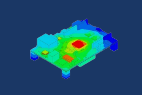
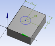
The course devotes very little time to CFD & thermal theory and focuses on the use of the software through workshops to solve practical problems. Workshops are focused on the electronics industry and include heat sinks, amplifiers, grilles, circuit boards and include various software features such as zoom-in modeling, compact models, hex dominant meshing and non conformal meshing.The import of board trace layers are also discussed and demonstrated.
Most workshops create geometry from scratch or import neutral CAD geometry as starting points. DRD encourages the students to bring a SAT or Parasolid file with them to the training (preferably a model from their workplace) for a little testing and discussion of their own problems to solve. DRD will also demonstrate the integration between CAD systems and Icepack in the Workbench environment. DRD has added a custom workshop to the course that transfers the thermal results from Icepak to Ansys Mechanical for thermal-stress analysis all within Workbench.
DRD conducts this course over two days. Most of the course material comes from Ansys, Inc.’s three day Introduction to Icepak course. Students will receive all of these materials and can work through and reference the additional material on their own time.
Lecture & Demo Topics
-
Overview of Icepack and User Interface
-
Pre-defined objects in Icepak
-
Model Setup and Transient Solution Controls
-
Mesh Features – Hex Dominant, Non-Conformal, Zoom-In Modeling
-
Postprocessing
-
Connection to CAD within Ansys Workbench
-
Thermal-stress analysis
Representative Workshops
-
Finned Heat Sink
-
RF Amplifier
-
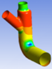
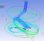
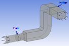
Cold-Plate Model with Non-Conformal Meshing
-
Multi-Level Meshing
-
Loss Coefficient for a Hexa-Grille
-
Transient Simulations
-
IDF Import
-
Integration of CAD with Ansys Workbench, Icepak, and Transfer of Results to Ansys Mechanical for Thermal-Stress Analysis
Course Enrollment and Schedule
Introduction to Ansys Icepak
by Mai Vang, Marketing Director | Jul 31, 2023
Ansys Twin Builder enables engineers to accurately and quickly design complex mechanical, power electronics and electrically controlled systems. In industries such as automotive, aerospace and industrial automation, organizations use Twin Builder to identify problems in the early design stages that other simulation or build-and-test methods cannot detect.
This course provides an introduction to Ansys Twin Builder for Mechanical Engineers. The course focuses on hands on workshops, and students solve problems ranging from spring-mass-damper dynamic systems to hydraulic systems including transient effects. Workshops also include modeling of a Pong game using co-simulation with the Ansys Mechanical Rigid Body Dynamics tool as well as use of Ansys Mechanical and Ansys CFD Reduced Order Models in fluid systems.
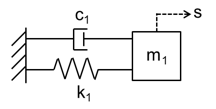
Workshop 1 - Spring-Mass-Damper Mechanical Systems
Workshop 1
Transient response of ideal single degree of freedom mechanical system (simple mass spring damper)
Workshop 2 - Hydraulic Systems including Transient Effects
Workshop 2
Transient and frequency response of ideal two degree of freedom mechanical system (simple multi-mass-spring-damper)
Workshop 3 - Co-Simulation using Ansys Mechanical Rigid Body Dynamics
Workshop 3a
Transient simulation of a hydraulic system comprised of ideal linear pipes and ideal pump
Workshop 3b
Transient simulation of a hydraulic system comprised of non-linear pipe and a realistic pump with feedback control
Workshop 4 - Hydraulic Systems with Ansys Mechanical Reduced Order Models
Workshop 4 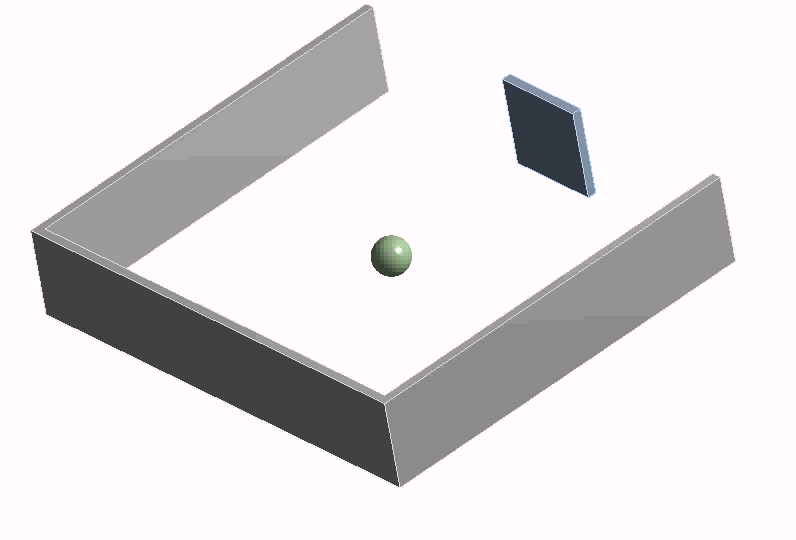
Transient simulation of ping-pong game with feedback control in Twin Builder using co-simulation with Rigid Body Dynamics (RBD)
Workshop 5 - Fluid Systems with Ansys CFD Reduced Order Models
Workshop 5
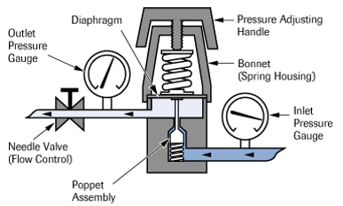
Transient simulation of gas regulator response in Twin Builder using Ansys Mechanical Reduced Order Model (ROM) to represent non-linear diaphragm structure.
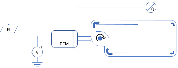
Workshop 6
Workshop 6
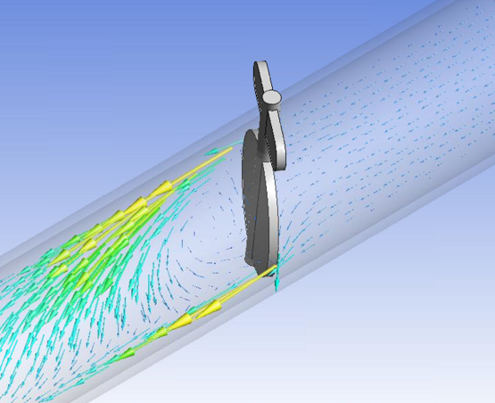
Transient simulation of piping system with position controlled butterfly valve where valve flow characteristics originate from an Ansys Fluent Reduced Order Model (ROM).
Course Enrollment and Schedule
Introduction to Ansys Twin Builder for Mechanical Systems
by Mai Vang, Marketing Director | Jul 30, 2023
This course focuses on essential Rocky DEM models and includes five hands on workshops. Particle shape representations, motion frames, and postprocessing will be discussed. Students will become proficient with the Rocky interface throughout the course with workshops that build on one another and expose progressively more advanced features.
Students are encouraged to be ready to discuss areas of Rocky application at their own companies.
Lecture 1: Intro to DEM
Lecture 1: Intro to DEM
This workshop introduces the Rocky interface and explores the use of conveyors with continuous particle inlets.
Workshop 1: Transfer Chute
Workshop 1: Transfer Chute
This workshop explores adhesion modeling, the volume fill approach for adding particles to a model and describes a common test model used to calibrate material data.
Workshop 2: Static Angle of Repose Test
Workshop 2: Static Angle of Repose Test
This workshop explores adhesion modeling, the volume fill approach for adding particles to a model and describes a common test model used to calibrate material data.
Workshop 3: Vibrating Screen
Workshop 3: Vibrating Screen
This workshop explains the use of motion frames in the context of oscillating motion. Particle size distribution definition is also discussed.
Workshop 4: SAG Mill
Workshop 4: SAG Mill
Surface wear and periodic boundaries are used in this workshop to demonstrate the behavior of a mill.
Workshop 5: Drop Weight Test
Workshop 5: Drop Weight Test
Freebody motion of boundaries as well as the Ab-T10 breakage model are highlighted in the final workshop of the course.
Course Enrollment and Schedule
Introduction to Ansys Rocky
by Mai Vang, Marketing Director | Jul 30, 2023
This course provides an introduction to conducting computational fluid dynamic simulations in Ansys CFX.
The course focuses on use of the DesignModeler and/or SpaceClaim to prepare CFD models for meshing within the Ansys Workbench meshing environment, and then pre and postprocessing with Ansys CFX.
The course devotes very little time to CFD theory and focuses on the use of the software through workshops to solve practical problems. Analysis types included in the course are generally turbulent with various functionality highlighted for each one – multiphase flow, conjugate heat transfer and fluid-structure interaction with Ansys FEA, or moving boundaries, for example.
Most workshops use neutral geometry in the form of SAT or Parasolid files for starting points. DRD encourages the students to bring a SAT or Parasolid file with them to the training (preferably a model from their workplace) for a little testing and discussion of their own problems to solve. Although most exercises will use either a SAT or Parasolid file, DRD will also demonstrate the integration between Ansys and CAD systems including associativity.
Chapter 1 - Overview of Workbench, DesignModeler, and Domain Extraction
Workshop 1a – Orientation of Workbench Interface and Sketching
In this workshop we introduce the Ansys Workbench environment and sketching in DesignModeler and/or SpaceClaim. A small model is created from scratch so the users gain some experience with the user interface.
Workshop 1b – Extraction of Fluid Domain
In this workshop we introduce the use of DesignModeler and SpaceClaim and the methods of creating a fluid domain from previously provided structural geometry.
Chapter 2 - Meshing a Fluid Domain for CFD Solutions
Workshop 2a – Element Types and Physical Behavior
This workshop demonstrates how to control creation of lower order versus higher order elements and tetrahedron versus brick elements in Mechanical. It also provides students the opportunity to compare solution accuracy and computational resources for models with lower and higher elements using the Mechanical solution information object.
Workshop 2b – Creating and Combining Multiple Domain Meshes
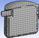
This workshop creates both a swept hexagonal mesh with boundary layer and a nonuniform tetrahedral mesh and combines them into a single domain for solving.
Workshop 2c – Multizone Meshing
This workshop uses the multizone mesher to produe a hex dominant mesh and hexacore mesh with and without inflation layers.
Chapter 3 - Overview of Single Phase CFD Analysis with Introduction to Fluid-Structure Interaction
Workshop 3 – Stress Analysis of a Pump Fluid End Using Direct and Iterative Solvers
This workshop demonstrates how to conduct a simple flow analysis in CFX and transfer the pressure boundary conditions to Mechanical for subsequent FEA analysis. Relative flow rates between the inlets are also examined.
Chapter 4 - Conjugate Heat Transfer
Workshop 4 – Conjugate Heat Transfer Simulation of Cooling Fin
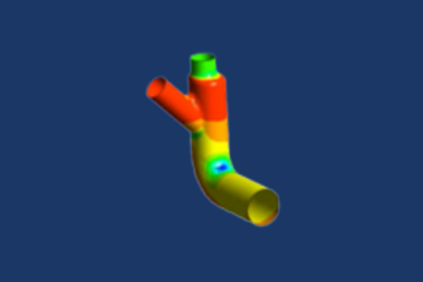
This workshop covers the creation of a conjugate heat transfer model between two different fluid domains and a tube with heat fins. Downstream flow temperatures and heat transfer coefficients for the fins are calculated.
Chapter 5 - Turbulence
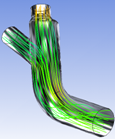
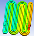
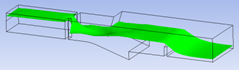
Workshop 5 – Model Simplification and Flow through a Serpentine Cavity
A serpentine cavity is extracted from a solid model, meshed with a boundary layer and the pressure drop across the model is found.
Chapter 6 - Multiphase Flow
Workshop 6 – Multiphase Flow in Sand Mixing Tank
For this workshop the fluid domain is extracted from a tank and then various sand and water flows are applied to the inlets of the tank. Initial locations of erosion is predicted along with the rate of erosion on the tank walls.
Chapter 7 - Transient Simulations and Thermal Analysis
Workshop 7 – Transient Thermal Analysis of an Electronics Package
For this workshop the fluid domain is extracted from a full 360 degree solid model. The heat source is surrounded by a circular heat sink to help convect away heat as 50W of energy is applied. The transient heat up is calculated.
Chapter 8 - MultiFrames of Reference, Cavitation
Workshop 8 – Free Surface Flow with Particles in an Open Channel
A fluid domain is extracted from solid geometry for this simulation. The mesh is created and multiphase flow with air and water is defined. In addition, particulates are added to the water and the analysis is solved as transient to examine particle flow.
Chapter 9 - Free Surface Flows
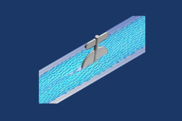
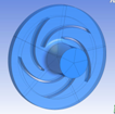
Workshop 9 – Rotating Impeller with Cavitation
The purpose of the tutorial is to model cavitation in a centrifugal pump, which involves the use of a rotation domain and the cavitation model.
Chapter 10 - Source Terms and Fan Modeling
Workshop 10 – Modeling Pressure Rise Using a Fan Curve and Filter with Source Terms
This workshop simulates a duct with a fan and filter. The fan is not explicitly modeled but a fan curve is used instead and the filter is modeled as a porous domain.
Course Enrollment and Schedule
Introduction to Ansys CFX
by Mai Vang, Marketing Director | Jul 30, 2023
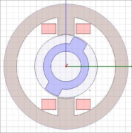
This 1-day course provides an introduction to electromagnetic analysis in Ansys Maxwell. This is an application-independent course, so it is useful to engineers looking to use Ansys Maxwell to model a variety of devices, like motors, generators, transformers, solenoids, and more.
The course commences with basic concepts including 2-D and 3-D magnetostatic, eddy current, electrostatic, and transient analyses. In addition to covering the different solvers and the relevant modeling techniques for each, the course will cover ways to efficiently pre- and post-process the engineer’s models in Maxwell, including parametric analyses.
During the course, students will build hands-on skills by setting up and solving a variety of simulation models during the workshop sections.
Workshop 1 – 3D Magnetostatic
Workshop 1 – 3D Magnetostatic
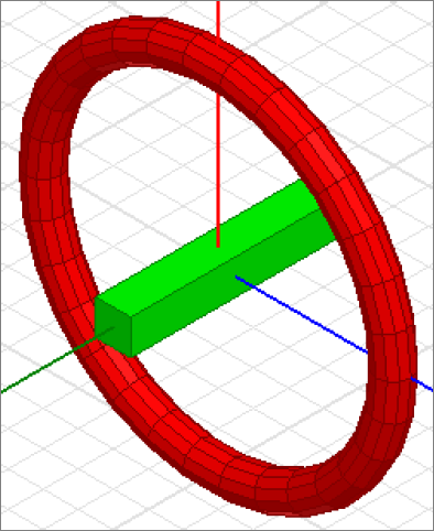
This workshop will discuss how to create geometry in Maxwell and use it to set up a torque calculation in the 3D Magnetostatic Solver.
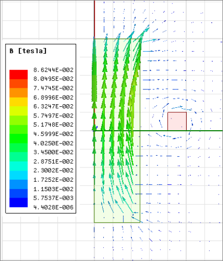
Workshop 2 – 3D Eddy Current
Workshop 2 – 3D Eddy Current
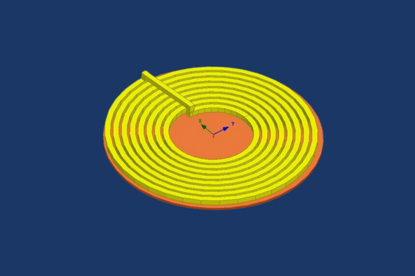
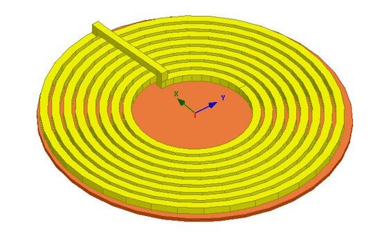
This workshop introduces the Eddy Current solver based on a simple example with a disk above a coil. The solver calculates the magnetic fields at a specified sinusoidal frequency. Both linear and nonlinear (for saturation effects) magnetic materials can be used. Also, eddy, skin and proximity effects are considered.
Workshop 3 – 2D Transient Magnetic
Workshop 3 – 2D Transient Magnetic
This workshop represents a quick start to using rotational motion. It will cover how to perform rotational motion in Maxwell 2D using a rotational actuator (experimental motor) example. The workshop covers three techniques: large rotation standstill, large rotation at constant speed, and large rotational transient motion.
Section 4- Postprocessing and Parameters
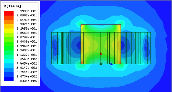
Workshop 4.1 – Postprocessing
This workshop will discuss how to use the Maxwell 2D Post Processor. Field plots and calculator operations will be demonstrated on an Eddy Current project. Some examples of postprocessed results in this workshop are contour/vector plots of the B field, graphing the H field magnitude along a designated path, and integrating the copper losses within the coils.
Workshop 4.2 – Parametric Analysis
This workshop describes the steps required to setup a parametric analysis offered through Optimetrics. A simple magnetostatic problem will be used to demonstrate the setup. The coil current and the dimensional length of an iron slug will be varied and the impact of changes in above parameters on the force exerted on the slug will be observed.
Course Enrollment and Schedule
Introduction to Ansys Maxwell