
Introduction to Ansys Mechanical
Introduction to Ansys Mechanical
Two-day courseThis course provides an introduction to the Ansys Mechanical Environment of the Ansys software product suite.
The course focuses on use of the Mechanical user interface, which is included in Ansys Mechanical Pro, Ansys Mechanical Premium, and Ansys Mechanical Enterprise. Within this interface you read CAD geometry, assign material properties, apply loads and boundary conditions, define mesh controls, perform solutions, review analysis results, and generate an automatic html report.
The course devotes some time to theory and concepts at a very basic and practical level. These topics include finite element concepts, solutions of simultaneous equations, and contact models. These portions of the course emphasize practical theory concepts, which engineers need to understand in order to do finite element analysis.
Chapter 1 - Overview of Mechanical
 Workshop 1 – Static Stress Analysis of a Fluid Connector
In this workshop we expose the user to the Ansys Workbench and Mechanical interfaces and perform a simple static stress analysis on the fluid connector. Basic file management is discussed as well.
Chapter 2 - General Overview of FEA
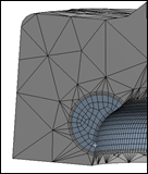
Workshop 2a – Element Types and Physical Behavior 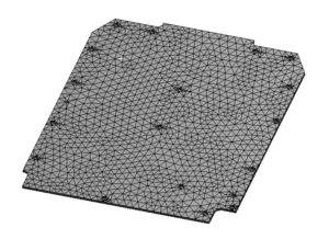
This workshop demonstrates how to control creation of lower order versus higher order elements and tetrahedron versus brick elements in Mechanical. It also provides students the opportunity to compare solution accuracy and computational resources for models with lower and higher elements using the Mechanical solution information object.
Workshops 2b – 2h. Mesh Controls on a Casting
This set of workshops demonstrate how to use some of the meshing techniques available in Mechanical to obtain accurate stresses with pinch controls, Multizone, Inflation, and Sphere of Influence methods .

Chapter 3 - Material Properties
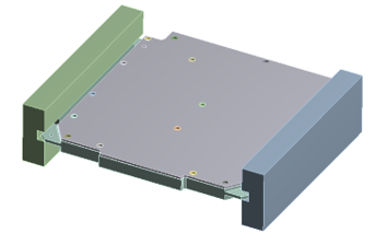
Workshop 3 – Assigning Material Properties to Parts in a PWB Assembly 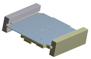
This workshop uses various WB techniques to assign material properties. The WB Engineering Data Module is discussed in detail.
Chapter 4 - Loads and Boundary Conditions for Structural Analysis
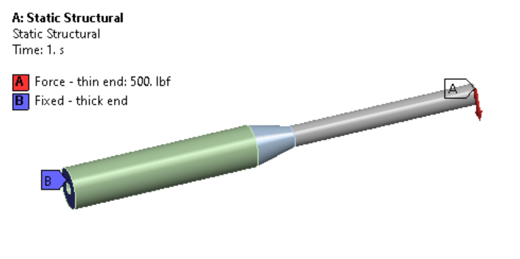
Workshop 4 – Stress Analysis of a Pump Fluid End With Multiple Load Conditions 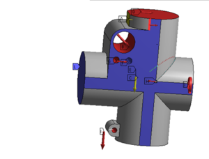
This workshop exposes all of the various structural loading options available within Mechanical.
Chapter 5 - Solution Options to Static Structural Analysis
Workshop 5 – Stress Analysis of a Pump Fluid End Using Direct and Iterative Solvers 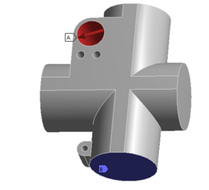
We start the solution with an assembly and suppress all of the parts, except one for analysis. We use mapped meshing to set up the mesh. We use solution options to control which solver Mechanical uses for a static solution, direct or iterative. We use the solution information object to monitor the solution and to determine which solver is faster. For the iterative solve we use a preprocessing command object to set the solution accuracy. We turn the weak spring option off and on to determine the effect of weak springs on the solution.
Chapter 6 - Evaluation of Analysis Results
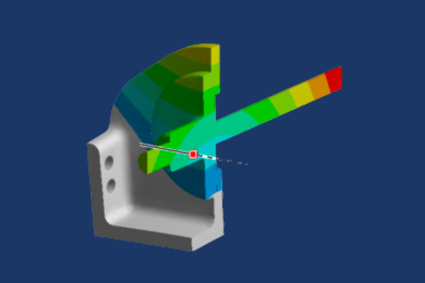
Workshop 6a – Stress Analysis of a Flanged Tube and Check of Results 
The primary purpose of this workshop is to provide students the opportunity to check the results of the finite element model using hand calculations based on closed form solutions. We use symmetry boundary conditions to perform analysis on a quarter model of the flanged tube. We define a local cylindrical coordinate system and then use it to calculate axial, radial, and hoop component stresses. Finally, we compare the finite element model component stresses with stresses calculated using closed form equations for thin and thick walled pressure vessels. Students discuss with the instructor the correlation between the finite element and hand calculated stresses.
Workshop 6b – Postprocessing Options, Introduction to Scoping and Convergence 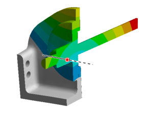
This workshop covers the extensive options available for results post-processing within Ansys Mechanical including cut planes, vector plots, legend manipulation, result display scaling, etc. We also get a first look at scoping of results and cover the concept of mesh convergence.
Chapter 7 - Evaluation of Local Stresses
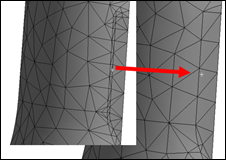
Workshop 7 – Stress Analysis of a Mechanical Link Using Scoping and Convergence 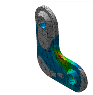
The focus of this workshop is use of scoping and convergence to evaluate local stresses. We start the workshop by doing stress analysis on a version of the link, which has a sharp corner, and students refine the mesh at the sharp corner to discover first hand the behavior of a stress singularity. Using model branching students add to the project a version of the link, which has a fillet where the sharp corner was present in the previous version. Students define a scoped stress object for stresses in the fillet and then use convergence to determine the stress to an accuracy of 2%.
Chapter 8 - Modal Analysis
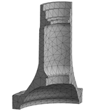
Workshop 8 – Modal Analysis of an Alternator Bracket with and without Prestress 
In this workshop we set up a model of an alternator bracket for normal modes analysis. We model the alternator attached to the bracket as a rigid point mass and monitor the change in natural frequencies and mode shapes as we change it to a deformable point mass. We also add standard earth gravity and note that Mechanical takes into account prestress effects if structural loads are present while performing a normal modes analysis.
Chapter 9 - Modeling Assemblies with Contacts
Workshop 9 – Stress Analysis of a Platform Assembly 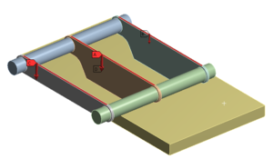
This workshop is designed to provide students with practice modeling assemblies. We read the assembly into Mechanical and perform static stress analysis using default bonded contact to hold the parts together. We then use model branching to make a new version of the model, which has no separation contact instead of bonded contact for some of the connections, and we compare the behavior of the models with bonded and no separation contact in the connections.
Chapter 10 - Modeling Assemblies with Joints
Workshop 10a – Modeling Joints in a Backhoe Lift Bucket Assembly 
This workshop is focused on connecting parts together with a sample of the many joint types available in Mechanical. It explores the use of the Joint Configure to preview the possible motion of the jointed mechanism, as well as the Redundancy Analysis tool to verify the joints are constraining the motion as desired. Also, it uses the ability to specify parts as rigid instead of flexible to simplify the model.
Workshop 10b – Modeling Joints in a Backhoe Assembly with a Single Hydraulic Cylinder
This workshop builds on the skills developed in the previous workshop by setting up joints on a more complex model. With the higher complexity of the mechanism analyzed in this workshop comes a higher possibility of mistakes, so this workshop focuses on best practices that will aid in building up the set of joints incrementally while verifying the joints at each step of the process.
Chapter 11 - Rigid Body Motion in Static Solutions
Workshop 11 – Stress Analysis of a Pipe and Plate Assembly with Rigid Body Motion 
This workshop teaches the user to identify and fix locations in a model that may have rigid body motion due to contact regions that are not correctly defined. We also show the usefulness of a Modal analysis in determining rigid body motion in a static model; rigid body motion causes zero frequency modes in a normal modes analysis.
Chapter 12 - Interaction with CAD
Workshop 12 – CAD Parameter Associativity of a Piston 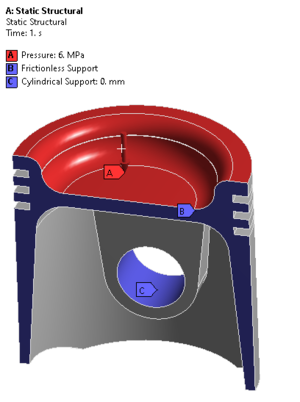
The purpose of this workshop is to demonstrate associativity between CAD software, Workbench, SpaceClaim, and Mechanical. The starting point for this workshop is a parametric model in SpaceClaim format. SpaceClaim functions as the ‘CAD’ system for this workshop; the same principles apply to CAD packages. We transfer the model to Ansys Mechanical, set up and solve the model in a simple stress analysis. We then make changes to the geometry using SpaceClaim, update the model in Mechanical and re-solve. We demonstrate the usefulness of the Design of Experiments functionality within Workbench.
Workshop A: Thermal-Stress Analysis of a Heat Exchanger
Workshop A: Thermal-Stress Analysis of a Heat Exchanger 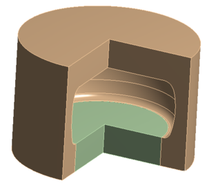
A first look at performing a thermal-stress analysis of a heat exchanger. The user is introduced to thermal loads, convection and temperature, and the model is solve. An energy balance is performed using the temperature reaction loads. Following this, the temperature profile of the heat exchanger is fed into a structural analysis through the Workbench project schematic and a simple structural analysis is performed.
Workshop B: Ansys Mechanical Integration with Ansys MAPDL (or Ansys Classic)
Workshop B: Ansys Mechanical Integration with Ansys MAPDL (or Ansys Classic) 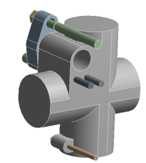
This workshop exposes the user to the integration of Mechanical with MAPDL, or Ansys Classic. The students create named selections within Mechanical as well as command objects and then transfer the model into MAPDL. The student explores using MAPDL for object selections, defining loads and solving the model. This workshop is a first look at using MAPDL commands to augment an Ansys Mechanical analysis.
Workshop B: Ansys Mechanical Integration with Ansys MAPDL (or Ansys Classic)
 Workshop B: Ansys Mechanical Integration with Ansys MAPDL (or Ansys Classic)
This workshop exposes the user to the integration of Mechanical with MAPDL, or Ansys Classic. The students create named selections within Mechanical as well as command objects and then transfer the model into MAPDL. The student explores using MAPDL for object selections, defining loads and solving the model. This workshop is a first look at using MAPDL commands to augment an Ansys Mechanical analysis.
Course Enrollment and Schedule
Introduction to Ansys Mechanical
Ansys Topology Optimization and Metal Additive Manufacturing
Ansys Topology Optimization and Metal Additive Manufacturing
one-day courseRevolutionary manufacturing techniques are making Topology Optimization a relevant design tool. Results that were previously theoretically correct but impractical to manufacture are now becoming more feasible as advances in 3D printing make Topology Optimization solutions manufacturable.
Ansys offers a full range of products that enable simulation of the entire workflow from Topology Optimization using Ansys Mechanical and faceted geometry cleanup using SpaceClaim to part orientation and support creation using Additive Prep and finally simulation of the Additive Manufacturing process using Workbench Additive.
This 1-day course will focus on Topology Optimization, faceted geometry cleanup, and metal Additive Manufacturing process simulation using Ansys Workbench Additive.
Module 1 - Topology Optimization Basics

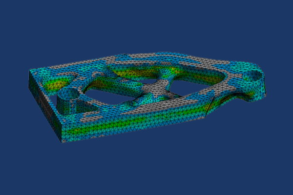
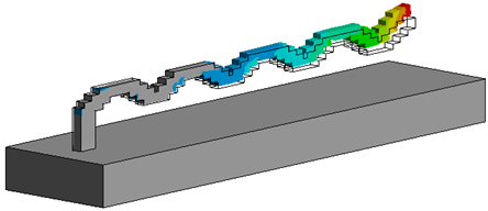
Workshop 1 — Michell Structure
This workshop demonstrates some of the basic capabilities of Topology Optimization to produce an optimized material configuration for the given Structural load case. The result is very similar to the optimum shape that was theorized by Australian Mechanical Engineer, A. G. M. Michell in the early 20th century
Module 2 – Basic Geometry Cleanup in SpaceClaim
Workshop 2 — Optimized Geometry Cleanup with Extract and Fit Curve Tools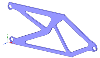
This workshop discusses the various postprocessing options within Ansys Workbench LS-DYNA involving global energy balance, ASCII time history output of contact forces, boundary condition reaction forces, etc. This workshop demonstrates some of the automated tools that can be used to clean up STL geometry from Topology Optimization analysis. Extract Curves and Fit Curves provide easy options for taking non-CAD geometry, which is commonly dirty surfaces, and turning it into smooth CAD surfaces.
Module 3 – Additive Manufacturing Process Simulation in Workbench
Workshop 3 — Optimized Geometry Cleanup with Automated Facet Tools
This workshop demonstrates some of the automated tools that can be used to clean up STL geometry from Topology Optimization analysis. Basic faceted geometry conversion, curve extraction, and curve fitting are used to create CAD geometry from STL geometry. A special meshing technique is then used to smooth over any faceted surfaces in Ansys Mechanical.
Module 4 – Full Workflow from Topology Optimization to Additive Manufacturing
Workshop 4 — Setting up a 3D Print Process Simulation
This workshop uses a very basic geometry to demonstrate how to set up and solve an Additive Manufacturing simulation using ANSYS Workbench Additive. This involves solving a Transient Thermal analysis to calculate the global temperature history of the process and then passing that data into a Static Structural analysis to solve for stresses, deformations, and other Structural results.
Course Enrollment and Schedule
Ansys Topology Optimization and Metal Additive Manufacturing
Ansys nCode DesignLife Training
Ansys nCode DesignLife
Two-Day CourseThe objective of this course is for attendees to develop a strong expertise in the use of Ansys nCode DesignLife for durability and fatigue analysis. The course also demonstrates several examples of setting up and solving DesignLife simulation within the native Mechanical GUI using the “Mechanical Embedded DesignLife” ACT extension. The course covers a broad array of topics focusing on stress life for high cycle fatigue to strain life for low cycle fatigue studies, duty cycle vibration fatigue to simulate virtual shaker table test, as well as seam weld fatigue on thin plate weldments meshed with shell finite elements to solid welds on thicker tubular structures.
The 2-day course includes training materials from Ansys, Inc. that delivers nine instructor-led lectures and ten workshops, as well as DRD Supplementary workshops that demonstrates additionally eight practical examples of fatigue covering different applications.
Prerequisites for this course are DRD’s Introduction to Ansys Mechanical course, and/or some level of proficiency with the Ansys Mechanical user interface.
Lecture 1: Introduction to CAE Fatigue
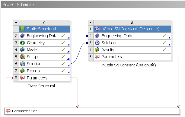
The goal of this workshop is to examine how Ansys nCode DesignLife interacts with Ansys Mechanical on the Workbench platform.
Lecture 2: HBM nCode (Standalone) Interface
Workshop 2.1: Constant Amplitude SN Fatigue Analysis Using HBM nCode Interface
The goal of this workshop is to examine how Ansys nCode DesignLife interacts with Ansys Mechanical on the Workbench platform.
Lecture 3: Workbench Integrated Interface
Workshop 3.1: Constant Amplitude SN Fatigue Analysis Using Workbench Integrated System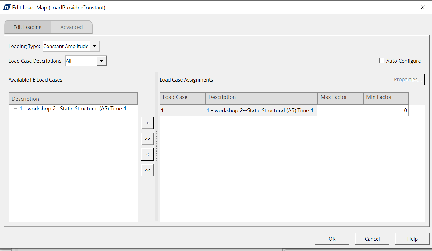
Workshop 3.2: Time Series SN Fatigue Analysis Using Workbench Integrated System
Lecture 4: Stress Life Fatigue Analysis Using Ansys nCode DesignLife
Workshop 4.1: Time Step SN Fatigue Analysis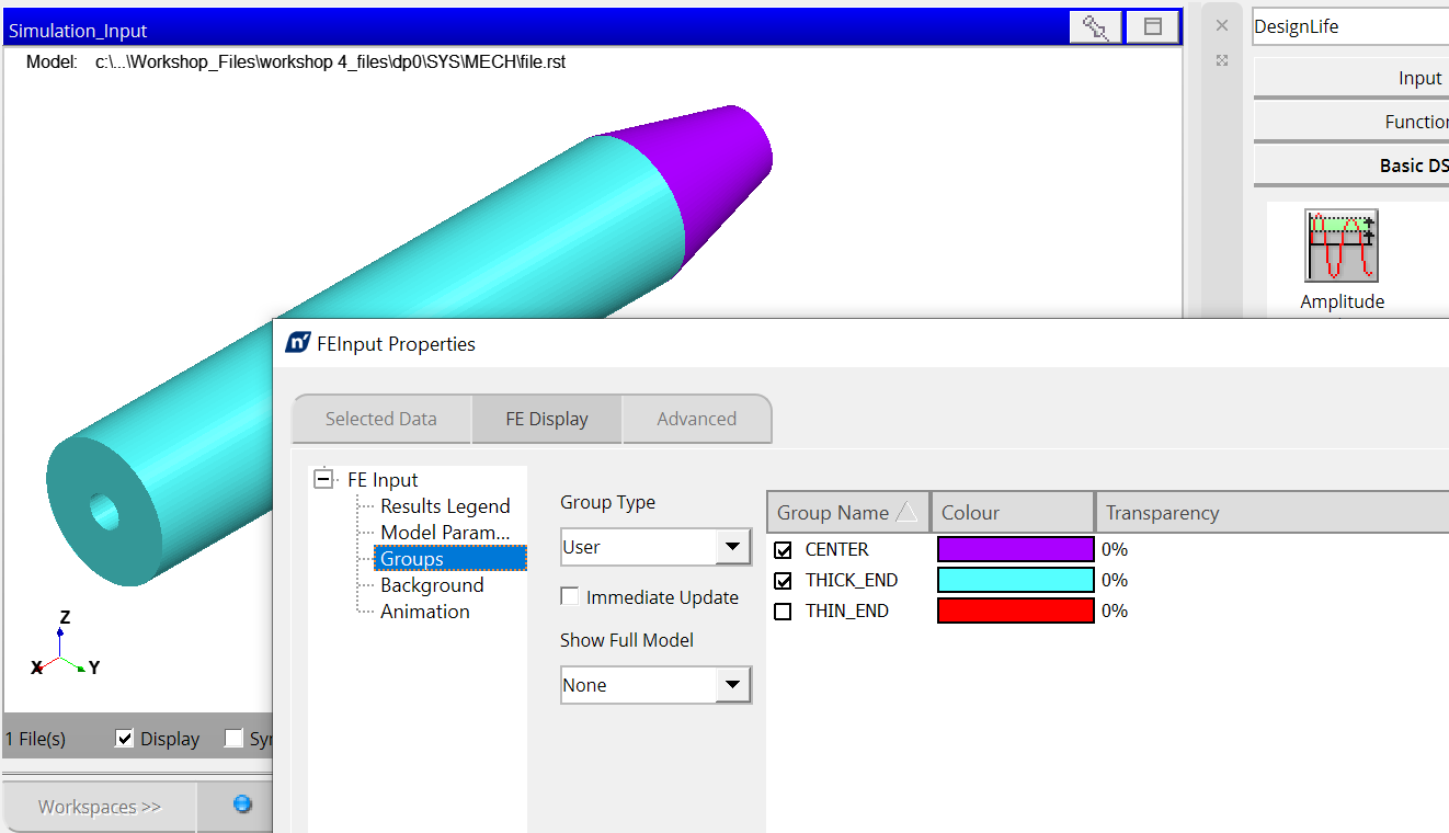
The goal of this workshop is to import FE model into Ansys nCode DesignLife, review the FE results and selectively choose subsets of the full model to run fatigue calculations.
Workshop 4.2: Stress Life Fatigue Analysis Using Add-On
Lecture 5: Strain Life Fatigue Analysis Using Ansys nCode DesignLife
Workshop5.1: Constant Amplitude EN Analysis with Mean Stress Correction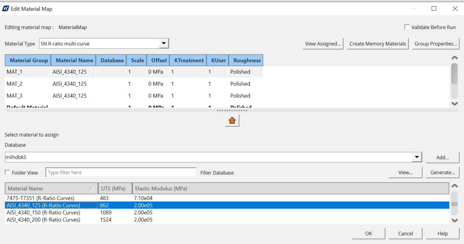
The goal of this workshop is to learn how to modify material mapping.
Workshop 5.2: Fatigue Evaluation of Wind Turbine Using Ansys nCode DesignLife
Workshop 5.3: Strain Life Fatigue Analysis Using Add-On
DRD Supplementary Workshops
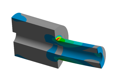
Workshop 1: Fatigue Analysis of a Simple Shaft under Combined Bending and Torsion Loads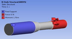
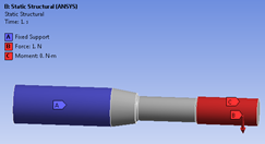
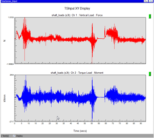
The goal of this workshop is to calculate the fatigue life of the drive shaft using Ansys nCode DesignLife time series loading. The stresses from unit bending and torsion load cases in Mechanical are paired with corresponding measured load histories to generate stress history that allows DesignLife to perform fatigue calculations using Rainflow Cycle Counting and damage assessment using Miner’s Rule.
Workshop 2: Fatigue Life Prediction for a Telecommunication Rack Subjected to El Centro Earthquake Seismic Loads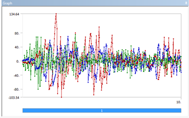
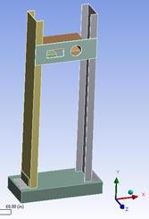
The goal of this workshop is to perform a full transient dynamic analysis within Ansys Mechanical and use the time history results to determine life of cabinet from this transient excitation in Ansys nCode DesignLife.
Workshop 3: Low Cycle Fatigue (LCF) using Nonlinear Stresses and Strains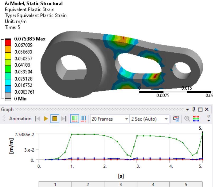
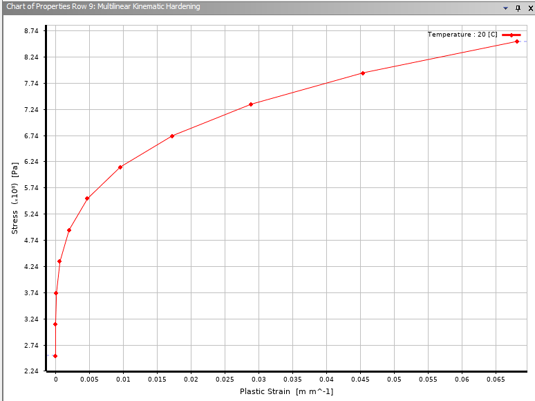
The goal of this workshop is to evaluate strain life fatigue using nonlinear stresses and strains from Ansys Mechanical. The nonlinear material characteristic is defined using the Multilinear Kinematic Hardening plasticity.
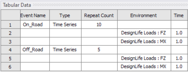
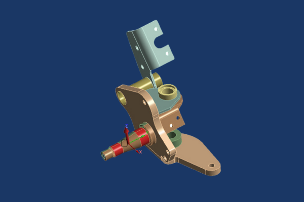
Workshop 4: Fatigue Analysis of a Trailer Spindle Subjected to Multiple Time Series Load Histories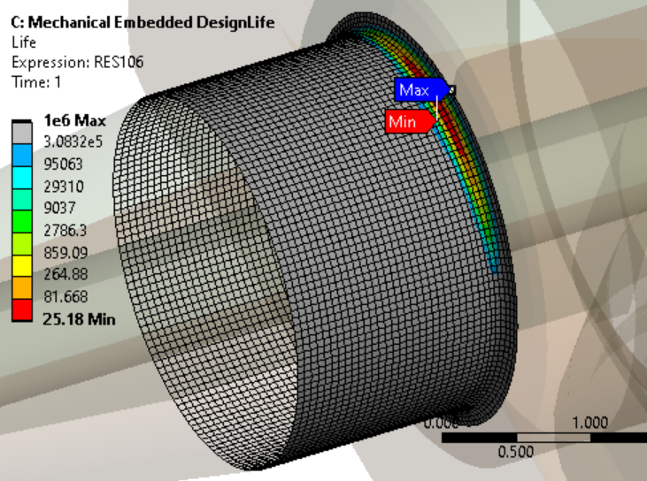
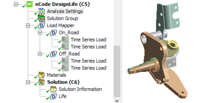
The goal of this workshop is to evaluate fatigue life of a trailer spindle subjected to duty cycle loading within Ansys Mechanical using Mechanical Embedded DesignLife ACT extension.
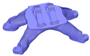
Workshop 5: Virtual Random Vibration Shaker Table Test of a Marine Alternator Bracket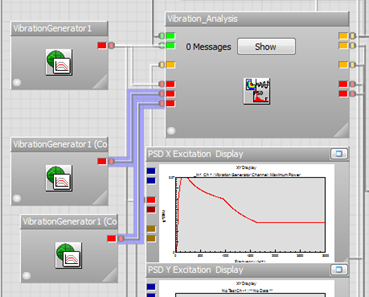
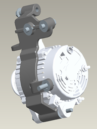
The goal of this workshop is to perform a vibration fatigue analysis using sequential multi-axis (3 axis) excitation of a marine alternator bracket to mimic a virtual shaker table test (VSTT) by using duty cycle loading in Ansys nCode DesignLife.
Workshop 6: Seam Weld Fatigue Analysis on a T-Joint Welded Assembly Meshed with Shell Finite Elements
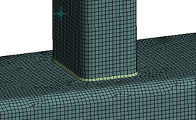
The goal of this workshop is to perform a seam weld fatigue analysis in Ansys nCode DesignLife using the shell weld finite element model results from Ansys Mechanical.
Workshop 7: Seam Weld Fatigue Analysis on a T-Joint Welded Assembly Meshed with Shell Finite Elements using the Mechanical Embedded
DesignLife ACT Extension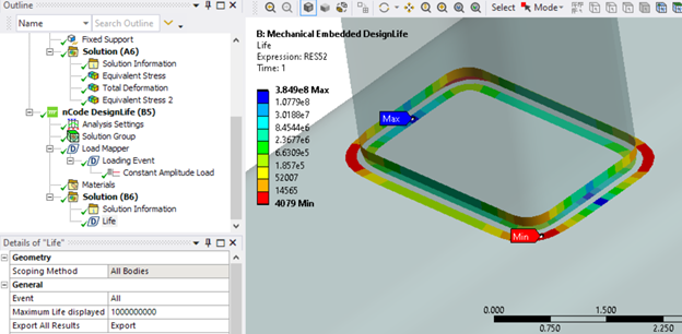
The goal of this workshop is to perform a seam weld fatigue analysis within Mechanical using the “MechanicalEmbeddedDesignLife” ACT extension.
Workshop 8: Seam Weld Fatigue Analysis on a T-Joint Welded Assembly Meshed with Solid Finite Elements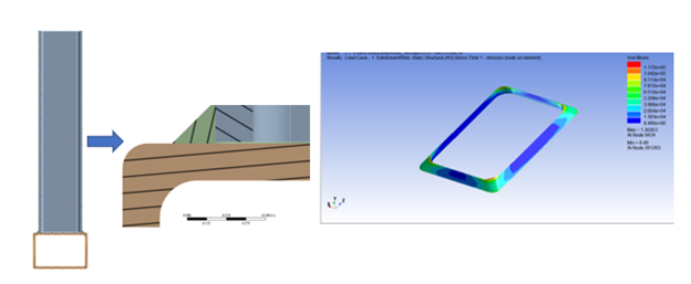
The goal of this workshop is to perform a seam weld fatigue analysis in Ansys nCode DesignLife using the solid weld finite element model results from Ansys Mechanical.
Course Enrollment and Schedule
Ansys nCode DesignLife Training
Ansys Mechanical Fatigue Life Prediction
Ansys Mechanical Fatigue Life Prediction
half-day courseThis course covers the use of the Ansys Mechanical Fatigue module available with Ansys Mechanical Pro, Ansys Mechanical Premium, and Ansys Mechanical Enterprise licenses. Fatigue tools enabled by nCode design life are not covered in this course.
The course offers a high level introduction to fatigue theory including stress life and strain life approaches. Mean stress corrections are discussed including Goodman, Soderberg, and Gerber methods for stress life calculations and Smith Watson Topper and Morrow methods for strain life calculations. Stress life workshops include simple non-proportional loading using solution combination and non-uniform load history utilizing the Rainflow counting method. The strain life workshop emphasizes proper use of mean stress correction techniques when calculating equivalent stress values for tensile vs compressive cases.
The course also includes two appendix workshops from DRD’s Ansys Mechanical Structural Dynamics course covering life predictions for random vibration and harmonic response analysis.
Prerequisites for this course are DRD’s Introduction to Mechanical course and some practical experience using Ansys Mechanical.
Chapter 1 - Introduction to Fatigue Theory and the ANSYS Mechanical Fatigue Module
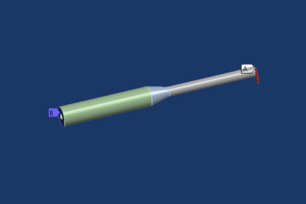
Workshop 1 - Stress Based Fatigue Life Prediction for a Shaft with Axial and Shear Loading using the ANSYS Fatigue Module
In this workshop we introduce the Mechanical Fatigue module to predict life on a stepped shaft using a stress based approach. Axial and bending load cases are calculated independently followed by solution combination for the simple non-proportional load case of fully reversed bending under constant axial tension. Goodman mean stress correction is implemented. Workbench parameterization is implemented to obtain fatigue life for various step radii values.
Workshop 2 - Fatigue Life Prediction for a Motorcycle Fender Bracket Using the Strain Life Method
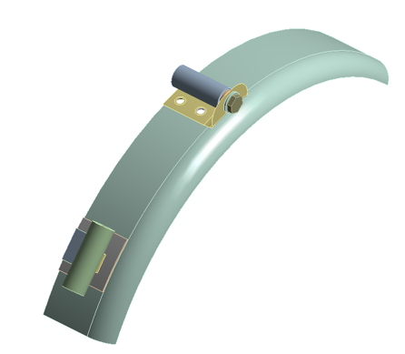
In this workshop, users implement a strain based approach within the Mechanical Fatigue Module for fully reversed loading near or exceeding the material yield strength. Morrow mean stress correction is implemented with emphasis on using the correct stress output for compressive mean stress adjustment.
Workshop 3 -Fatigue Analysis of a Trailer Spindle Subjected to Time Series Load History
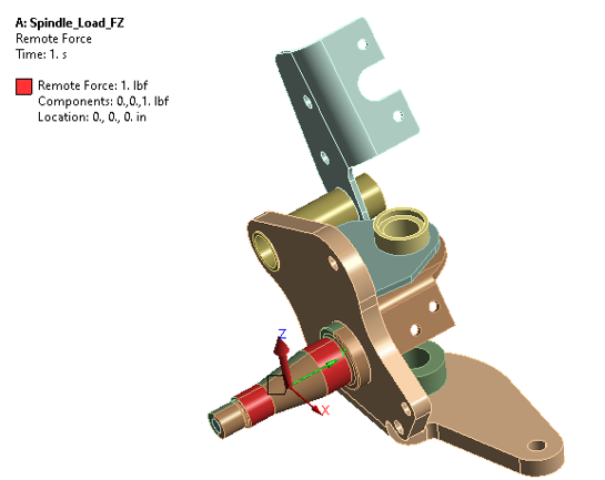
In this workshop, users learn how to import unidirectional time history load data from a test track into the Mechanical Fatigue Module. Stress life calculations are performed using Rainflow methodologies for various amplitude vs mean stress bin values with Goodman mean stress correction. Emphasis on the tradeoff between accuracy and solver time with respect to binning is given.
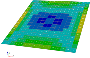
Dynamics Workshop 2 - Random Vibration Analysis of a PWB Assembly
In this workshop, students define a random vibration PSD spectrum and learn how to calculate 1 sigma, 2 sigma, and 3 sigma stresses. Fatigue life is calculated using the Steinberg Method. Students learn how to create a user defined result to calculate zero crossing frequency and validate the Mechanical Fatigue Module results using hand calculations.
Dynamics Workshop 8a -Harmonic Response Analysis of an Engine Alternator Bracket
In this workshop, students learn how to calculate maximum stresses and deflections on a motor bracket subject to harmonic loading. Students utilize the Mechanical Fatigue Module to calculate the expected time to failure of the bracket when the harmonic load frequency corresponds to the first natural frequency.