by Mai Vang, Marketing Director | Jun 27, 2023
This course provides workshops demonstrating the Shooting Bouncing Ray (SBR+) solver and antenna placement, using the ANSYS HFSS environment of the ANSYS Electronics Desktop (AEDT) Suite. This tool is included in the ANSYS HFSS Premium and ANSYS Electronics Enterprise licenses.
The course focuses on utilizing the SBR+ solution design type and performing antenna placement analysis. Within this course, one will analyze the electrical behavior of an antenna near a large 3D component (such as the body of a car) and understand how SBR+ utilizes less computational resources for more efficient simulations. In addition, predicting the coupling between two or more antennas while employing the SBR+ solver and large 3D components is demonstrated.
Most workshops begin with projects where CAD geometry has already been prepared or is drawn in the tool as part of the exercise. DRD encourages students to bring ACIS files with them to the training (preferably from their workplace) if they desire to test their own antenna geometry.
Module 1: Introduction & 3D Component
Workshop 1.1 — PIFA Antenna 3D Component 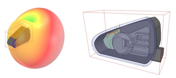
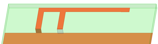
This workshop demonstrates how HFSS can be used to design and analyze an 800 MHz PIFA (planar inverted-F antenna) element, including the chassis that makes up this entire antenna module.
Module 2: Antenna Placement
Workshop 2.1 — SBR+ Platform Integration 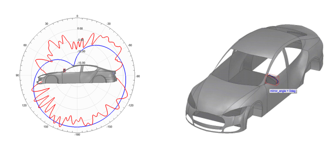
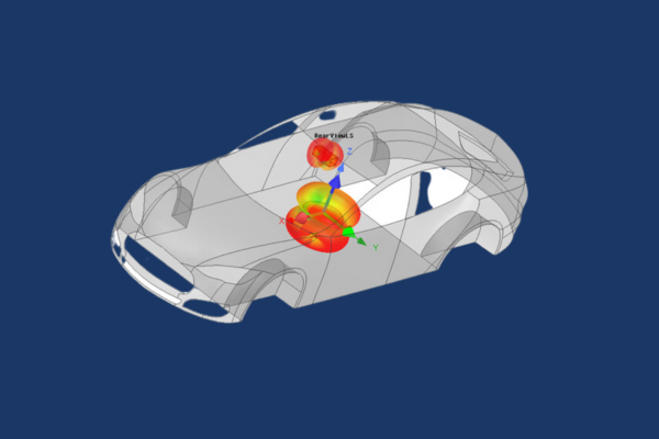
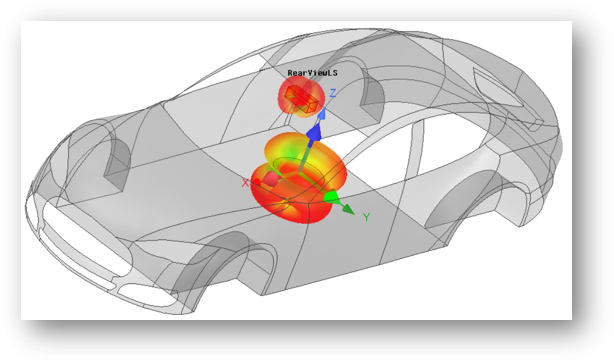
This workshop uses HFSS and SBR+ (Shooting Bouncing Ray) to analyze and predict the performance of an antenna integrated on to an electrically large platform, a car body.
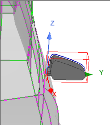
Workshop 2.2 — Side Mirror Near Field Link 
This workshop uses HFSS and SBR+ solution type design to analyze and predict the performance of an antenna linked to a car body.
Module 3: Antenna Coupling
Workshop 3.1 — Far Field Antenna to Antenna Coupling
This workshop demonstrates how an SBR+ design type can be used in HFSS to simulate the coupling between two different antennas.
Module 4: Car Garage Visual Ray Tracing (VRT)
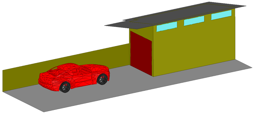
Workshop 4.1 — Vehicle to Home Communication with SBR+
This workshop analyzes coupling between a vehicle mounted antenna and a home Wi-Fi antenna.
Course Enrollment and Schedule
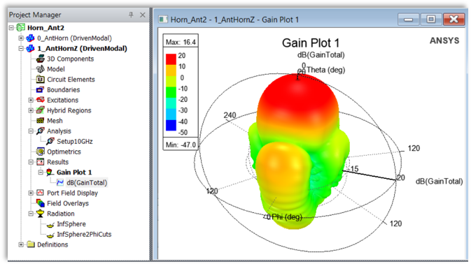
HFSS SBR+ Antenna Placement Design
by Mai Vang, Marketing Director | Jun 23, 2023
This course provides workshops, emphasizing on antennas, using the ANSYS HFSS environment of the ANSYS Electronics Desktop (AEDT) Suite. The general problem addressed is that of the high frequency electromagnetic field and antenna analysis.
The course focuses on the set-up and analysis of antenna simulations via the HFSS user interface. This tool is included in the ANSYS HFSS Premium and ANSYS Electronics Enterprise licenses. Within this interface, one can create CAD geometry of Antennas to analyze the near/far fields, surface currents, impedance, and S-parameters. One can also use the Antenna Design Toolkit (ATK) wizard to create common antenna geometry for ease of simulation design.
Most workshops begin with projects where CAD geometry has already been prepared or is drawn in the tool as part of the exercise. DRD encourages students to bring ACIS files with them to the training (preferably from their workplace) if they desire to test their own antenna geometry.
Module 1: Far and Near Fields
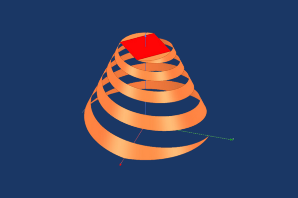
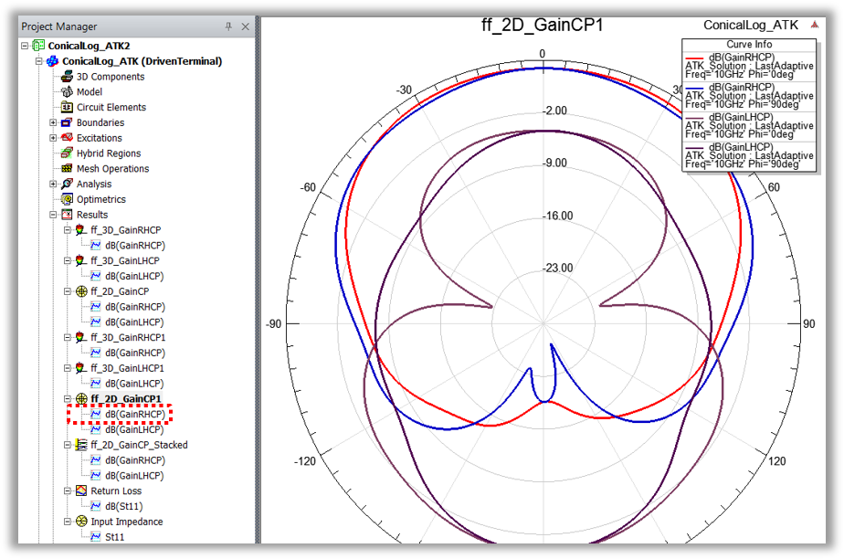
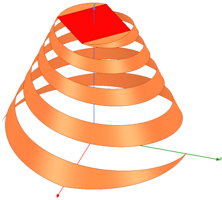
Workshop 1.1 — Conical Spiral Antenna with HFSS Antenna Toolkit
This workshop synthesizes a design for a conical spiral antenna using the ACT Extension HFSS Antenna Toolkit and generates the simulation reports and plots.
Workshop 1.2 — Dipole Antenna Far Fields
This workshop starts with a new HFSS project and HFSS design. A dipole antenna is chosen from the Component Library as a starting point for the geometry and the excitation.
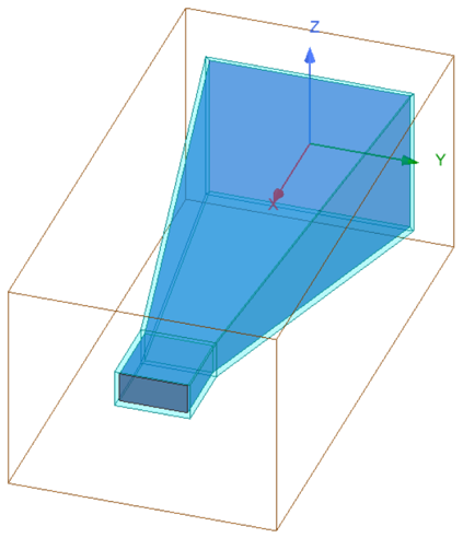
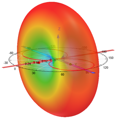
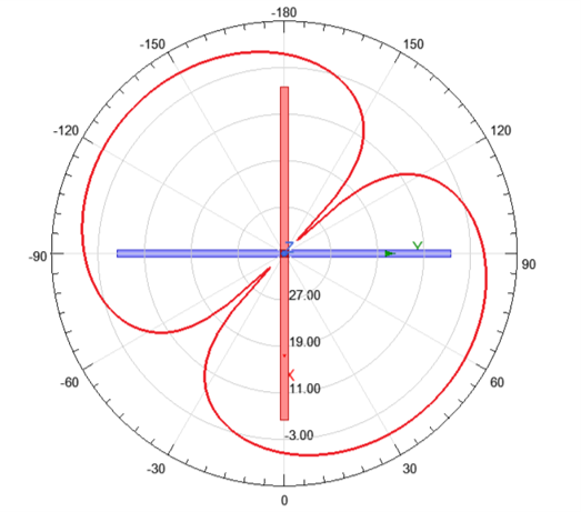
Workshop 1.3 — Horn Antenna Far Field Components
This workshop starts with an HFSS horn design and an incomplete setup. The initial orientation of the horn, relative to the coordinates, has the X-axis at boresight.
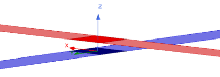
Workshop 1.4 — Crossed Dipole Antenna Near Fields
This workshop starts with two crossed dipole antennas. After initial simulation, and viewing the results, several near field quantities are plotted and exported.
Module 2: Sources and Field Quantities
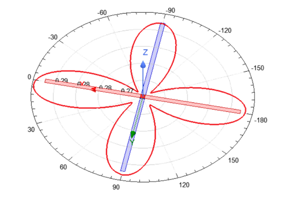
Workshop 2.1 — Crossed Dipole Antenna Sources
This workshop starts with two crossed dipole antennas and demonstrates how to plot far field using a far field infinite sphere setup.
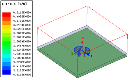
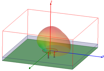
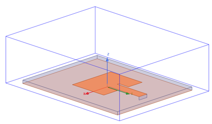
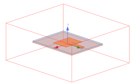
Workshop 2.2 — Circularly Polarized Patch Antenna
This workshop focuses on Antenna post-processing such as radiation patterns and plotting 2D & 3D fields on Antenna geometry.
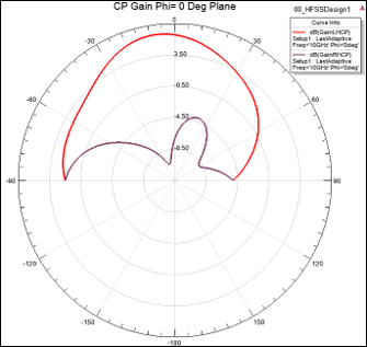
Workshop 2.3 — Circular Polarization Patch Advanced Field Quantities
This advanced workshop evaluates patch antenna S-parameters data, plotted solved fields, and pattern data.
Module 3: Boundaries
Workshop 3.1 — Patch Antenna Open Region Boundaries
This workshop demonstrates two approaches to creating open boundaries and gain insight about both approaches by seeing them applied to the same structure.
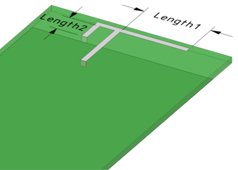
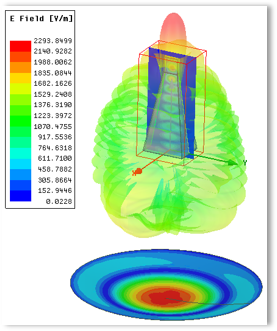
Workshop 3.2 — PIFA Boundaries: ABC PML FE-BI
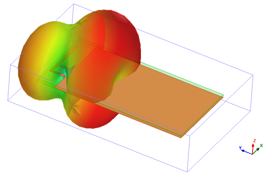
This workshop demonstrates creating boundaries, such as Absorbing Boundary Condition (ABC), Perfectly Match Layer (PML), and Finite Element – Boundary Integral (FE-BI) for a Planar Inverted – F Antenna.
Module 4: Dynamic Link
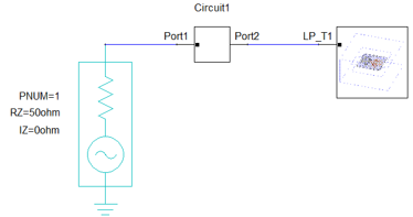
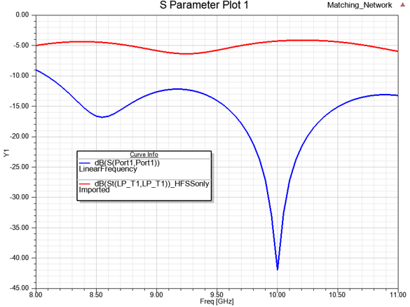
Workshop 4.1 — Dynamic Link
This workshop demonstrates how to dynamically link an HFSS design into a circuit simulation, use the Smith Tool in circuit design to match the antenna using lumped components, and push excitations from the circuit design to the HFSS design.
Module 5: Optimization
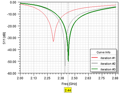
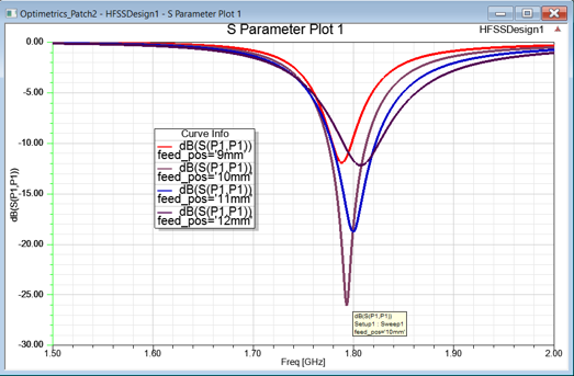
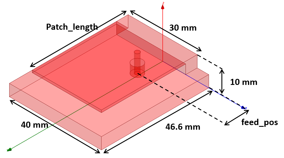
Workshop 5.1 — Antenna Optimetrics
This workshop demonstrates how to set up a parametric study, optimize, and simulate the Analytic Derivatives of a probe-fed patch antenna.
Workshop 5.2 — OptiSLang Derivatives Optimization of PIFA
This workshop demonstrates the derivative-based optimizer to optimize a planar inverted-F antenna (PIFA) design.
Module 6: HFSS Integral Equation (IE)
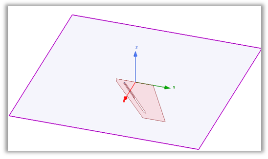
Workshop 6.1 — HFSS IE Blade Antenna
This workshop demonstrates how to set up, simulate, and analyze an airplane-mounted plane (blade) antenna using the Integral Equation (IE) solver.
Module 7: Formulations
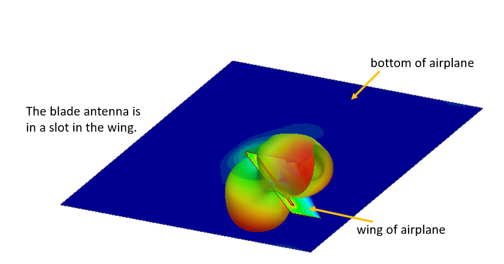
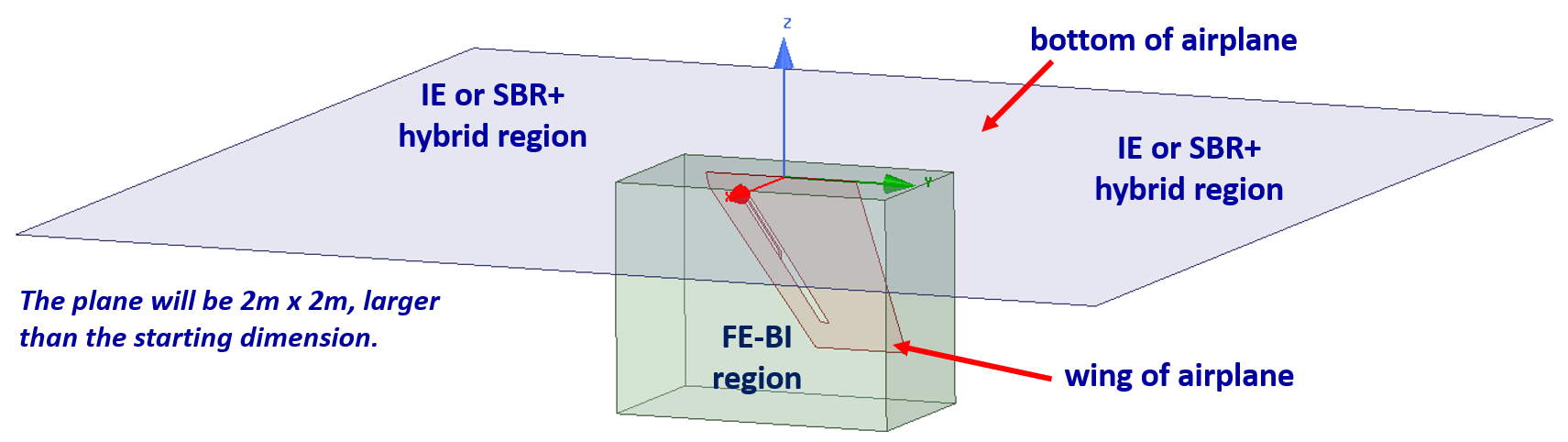
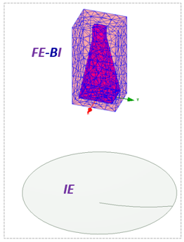
Workshop 7.1 — FE-BI Blade Antenna
This workshop sets up, simulates, and compares simulations of the airplane-wing mounted blade antenna. The large, flat geometry, representing an airplane fuselage, is simulated with both IE (Integral Equation) and SBR+ (Shooting Bouncing Rays).
Module 8: Hybrid Regions
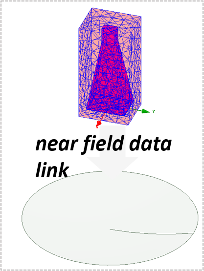
Workshop 8.1 — Data Linked Simulation of a Reflector Antenna
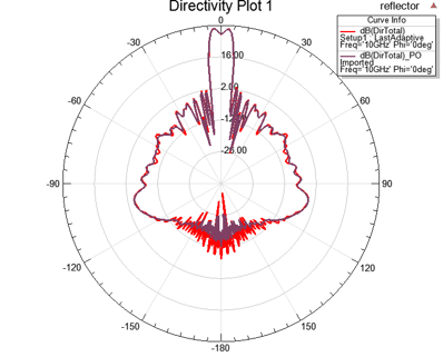
This workshop will demonstrate near field simulation results from a horn antenna and will feed a reflector antenna through a data link while also comparing the result of the Integral Equation (IE) and Physical Optics (PO) solvers.
Workshop 8.2 — Hybrid FEM-FEBI Simulation of a Reflector Antenna
Workshop 8.3 — Hybrid FEM-FEBI Antenna Placement Study
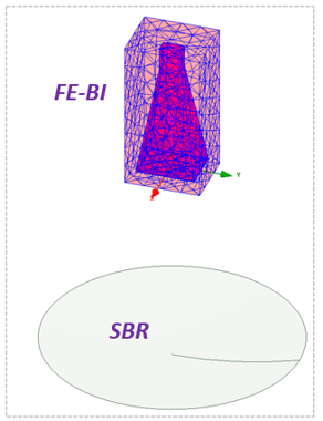
This workshop will demonstrate radiation field results when using a Finite Element-Boundary Integral (FE-BI) region on the horn antenna and use a Integral Equation (IE) solver on the reflector.
Course Enrollment and Schedule
Ansys HFSS Antenna Design


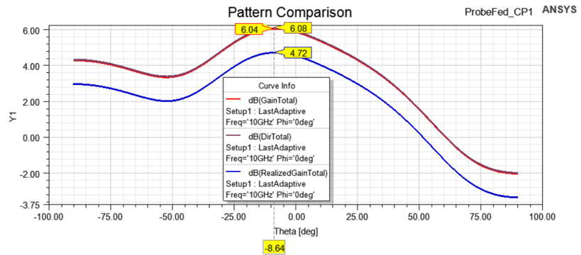

 This workshop demonstrates how to set up a parametric study, optimize, and simulate the Analytic Derivatives of a probe-fed patch antenna.