by Mai Vang | Sep 13, 2023
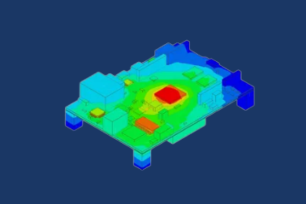
This course provides an introduction to conducting thermal simulations for electronics in Ansys Icepak using the Classic interface.
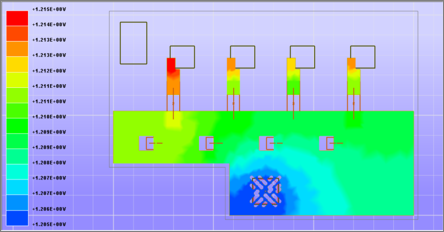
The course devotes very little time to CFD & thermal theory and focuses on the use of the software through workshops to solve practical problems. Workshops are focused on the electronics industry and include heat sinks, amplifiers, grilles, circuit boards and include various software features such as zoom-in modeling, compact models, hex dominant meshing and non conformal meshing.The import of board trace layers are also discussed and demonstrated.
Most workshops create geometry from scratch or import neutral CAD geometry as starting points. DRD encourages the students to bring a SAT or Parasolid file with them to the training (preferably a model from their workplace) for a little testing and discussion of their own problems to solve. DRD will also demonstrate the integration between CAD systems and Icepack in the Workbench environment. DRD has added a custom workshop to the course that transfers the thermal results from Icepak to Ansys Mechanical for thermal-stress analysis all within Workbench.
DRD conducts this course over two days. Most of the course material comes from Ansys, Inc.’s three day Introduction to Icepak course. Students will receive all of these materials and can work through and reference the additional material on their own time.
Lecture & Demo Topics
-
Overview of Icepack and User Interface
-
Pre-defined objects in Icepak
-
Model Setup and Transient Solution Controls
-
Mesh Features – Hex Dominant, Non-Conformal, Zoom-In Modeling
-
Postprocessing
-
Connection to CAD within Ansys Workbench
-
Thermal-stress analysis
Representative Workshops
-
Finned Heat Sink
-
RF Amplifier
-
Cold-Plate Model with Non-Conformal Meshing
-
Multi-Level Meshing
-
Loss Coefficient for a Hexa-Grille
-
Transient Simulations
-
IDF Import
-
Integration of CAD with Ansys Workbench, Icepak, and Transfer of Results to Ansys Mechanical for Thermal-Stress Analysis
Course Enrollment and Schedule
Introduction to Ansys Icepak
by Mai Vang | Jul 30, 2023
This 1-day course provides an introduction to electromagnetic analysis in Ansys Maxwell. This is an application-independent course, so it is useful to engineers looking to use Ansys Maxwell to model a variety of devices, like motors, generators, transformers, solenoids, and more.
The course commences with basic concepts including 2-D and 3-D magnetostatic, eddy current, electrostatic, and transient analyses. In addition to covering the different solvers and the relevant modeling techniques for each, the course will cover ways to efficiently pre- and post-process the engineer’s models in Maxwell, including parametric analyses.
During the course, students will build hands-on skills by setting up and solving a variety of simulation models during the workshop sections.
Workshop 1 – 3D Magnetostatic
Workshop 1 – 3D Magnetostatic 
This workshop will discuss how to create geometry in Maxwell and use it to set up a torque calculation in the 3D Magnetostatic Solver.
Workshop 2 – 3D Eddy Current
Workshop 2 – 3D Eddy Current 
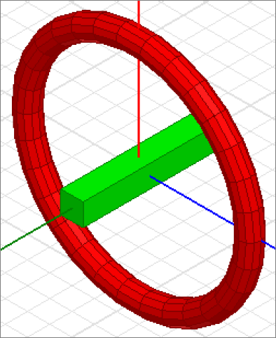
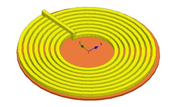
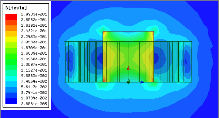
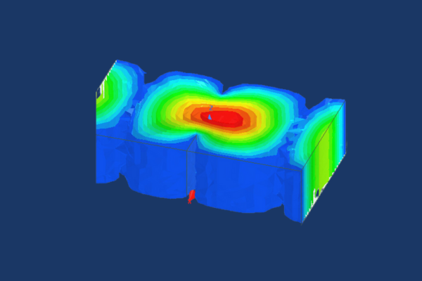
This workshop introduces the Eddy Current solver based on a simple example with a disk above a coil. The solver calculates the magnetic fields at a specified sinusoidal frequency. Both linear and nonlinear (for saturation effects) magnetic materials can be used. Also, eddy, skin and proximity effects are considered.
Workshop 3 – 2D Transient Magnetic
Workshop 3 – 2D Transient Magnetic 
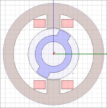
This workshop represents a quick start to using rotational motion. It will cover how to perform rotational motion in Maxwell 2D using a rotational actuator (experimental motor) example. The workshop covers three techniques: large rotation standstill, large rotation at constant speed, and large rotational transient motion.
Section 4- Postprocessing and Parameters
Workshop 4.1 – Postprocessing 
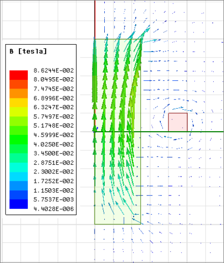
This workshop will discuss how to use the Maxwell 2D Post Processor. Field plots and calculator operations will be demonstrated on an Eddy Current project. Some examples of postprocessed results in this workshop are contour/vector plots of the B field, graphing the H field magnitude along a designated path, and integrating the copper losses within the coils.
Workshop 4.2 – Parametric Analysis 
This workshop describes the steps required to setup a parametric analysis offered through Optimetrics. A simple magnetostatic problem will be used to demonstrate the setup. The coil current and the dimensional length of an iron slug will be varied and the impact of changes in above parameters on the force exerted on the slug will be observed.
Course Enrollment and Schedule
Introduction to Ansys Maxwell
by Mai Vang | Jul 30, 2023
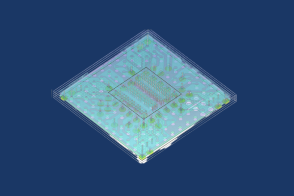
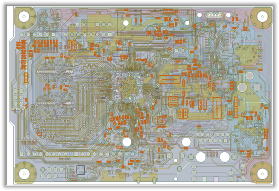
This course provides an introduction to the ANSYS SIwave environment of the ANSYS Electronics Desktop (AEDT) Suite. The general problem addressed is that of the PCB type. The course focuses on the use of the SIwave user interface and briefly touches on the HFSS 3D Layout interface. Both of these tools are included in the ANSYS SIwave Premium and ANSYS Electronics Enterprise licenses. Within these interfaces, one can import ECAD geometry, assign material properties, apply excitations, perform solutions, review analysis results, and generate several types of automatic html reports. We discuss solutions to general electromagnetic problems encountered by most PCB designers. Approaches for calculating trace characteristic impedence, crosstalk, DCIR drop/ohmic loss, S-parameters, signal/power integrity, and capacitor decoupling are addressed.
Most workshops begin with projects where ECAD geometry has already been prepared. DRD encourages students to bring ODB++ or ANSYS EDB files with them to the training (preferably from their workplace) if they desire to test their own geometry.
Module 1 - Overview of SIwave and SIwave Basics
Workshop 1.1 — Layout Design Import 
This workshop introduces the SIwave import process and utilities applicable to starting many or most SIwave projects.
Workshop 1.2 — PCB Z0 and Crosstalk Scan
This workshop shows how to automatically and quickly scan the entire PCB or package layout and identify violations with regards to delay, impedance profiles, and crosstalk susceptibility.


Module 2 - Signal Integrity
Workshop 2.1 — Channel S-Parameter Extraction 
This workshop shows the process of setting up ports and extracting the S-parameters for a high-speed channel using ANSYS SIwave.
Workshop 2.2 — TDR Wizard 
This workshop shows the process of setting up a TDR simulation in ANSYS SIwave to plot the transient impedance variation of single-ended and differential nets. The ANSYS Electronics Desktop Circuit capability is used for the transient simulation.
Workshop 2.3: Parametric Analysis
This workshop shows the process of setting up ports, clipping the design and studying the insertion loss variation by sweeping parameters.

Module 3 - Power Integrity
Workshop 3.1: Package PDN RLCG Extraction 
This workshop shows the process of setting up ports and extracting PDN (power distribution network) parasitics for a package design in ANSYS SIwave.
Workshop 3.2a: DC IR Drop Analysis 
This workshop shows the process of setting up a DCIR simulation for a PCB design and validating the electrical performance by identifying regions of current crowding and high current vias for a single-phase VRM system. This workshop also shows how to obtain tabular data for the current and resistance for the vias, and obtain loop resistance and inductance values from the VRM to the IC.
Workshop 3.2b: SIwave DCIR Multi-phase VRM 
This workshop shows the process of setting up a DCIR simulation for a PCB design and validating the electrical performance by identifying regions of current crowding and high current vias for a multi-phase VRM system. This workshop also shows how to obtain tabular data for the current and resistance for the vias, and how to obtain loop resistance and inductance values from the VRM to the IC.
Workshop 3.3: Decoupling Optimization
This workshop shows the process of setting up an ANSYS SIwave PI Advisor simulation, for a PCB design, to validate and optimize the decoupling strategy using ANSYS SIwave.


Course Enrollment and Schedule
Introduction to Ansys SIwave
by Mai Vang | Jul 30, 2023
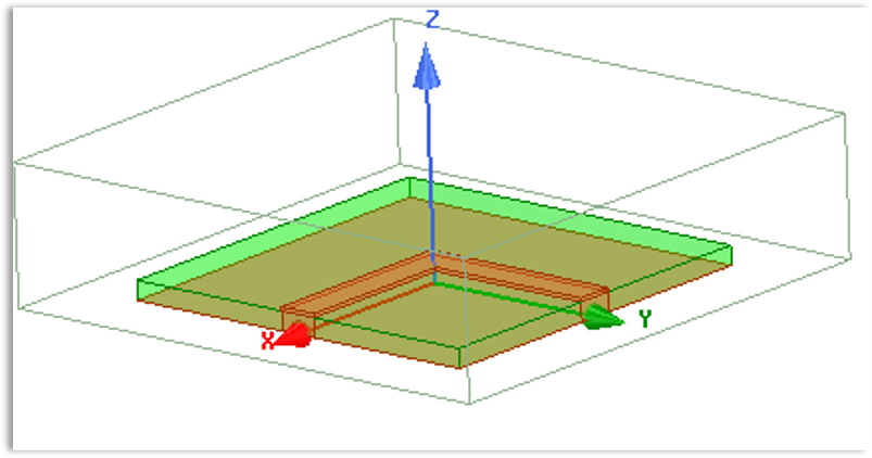
This course provides an introduction to the HFSS environment of the Ansys Electronics Desktop (AEDT) Suite. The general problem addressed is that of the high frequency electromagnetic field. The course focuses on the use of the HFSS user interface. This tool is included in the Ansys HFSS Premium and ANSYS Electronics Enterprise licenses. Within this interface, one can create CAD geometry, import CAD geometry, assign material properties, apply excitations, perform solutions, and review analysis results.
The course presents solutions to general electromagnetic problems encountered by most antenna/RF designers. Approaches for calculating characteristic impedance, S-parameters, electric/magnetic fields, and near/far fields are covered. Most workshops begin with projects where CAD geometry has already been prepared or is drawn in the tool as part of the exercise. DRD encourages students to bring ACIS files with them to the training (preferably from their workplace) if they desire to test their own geometry.
Module 1: Overview of HFSS
Workshop 1.1 — Band Pass Filter Simulation
This workshop introduces the HFSS application via a previously set up simulation of a microwave band pass filter.
Module 2: Boundaries and Simulation Space
Workshop 2.1 — Patch Antenna Open Region
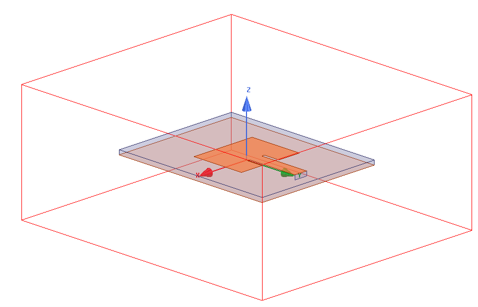
This workshop starts with a project that does not yet have the open region boundary assigned. The user will create both the region air box and the radiation boundary assignment.
Workshop 2.2 — Coax Bend Finite Conductivity Boundary 
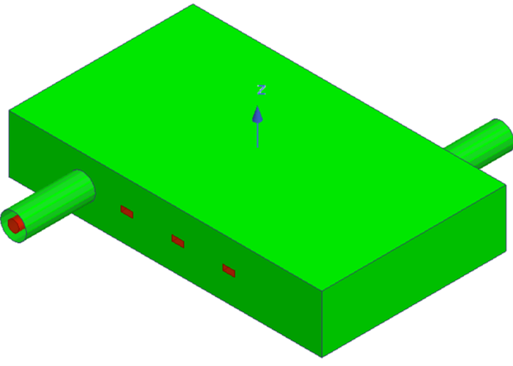
This workshop demonstrates how to change the default PEC boundary on an HFSS coaxial bend model to a finite conductivity boundary.
Module 3: HFSS FEM Solution Setup
Workshop 3.1 — SMA Stub Auto Solution Setup 
This workshop demonstrates a HF simulation of an SMA Coax Microstrip Stub and the resulting S-parameters.
Workshop 3.2 — Band Pass Filter Broadband Mesh 
This workshop demonstrates the broadband mesh capabilities of HFSS on a microwave filter simulation.
Module 4: Simulation Post Processing
Workshop 4.1 — Coax Tee S-Parameters and Fields 
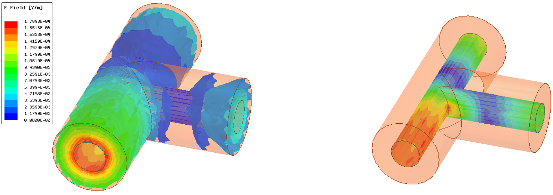
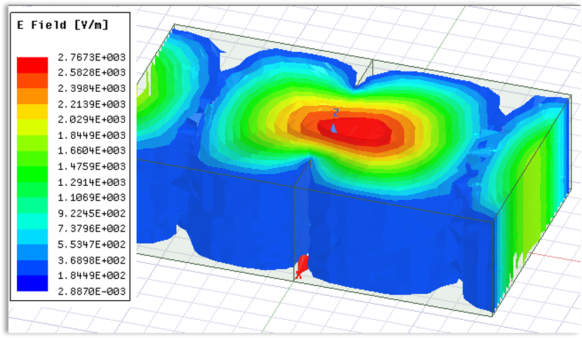
This workshop on HFSS post-processing focuses on rectangular plots of S-parameters and field plots on a simple coaxial “T” geometry.
Workshop 4.2 — Patch Antenna Smith Chart and Field Plots
This workshop demonstrates plotting the S-parameters of a patch antenna in Smith Chart format, as well as plotting electric fields on a surface.
Module 5: Geometry Construction
Workshop 5.1 — Microstrip Bend Geometry Construction 
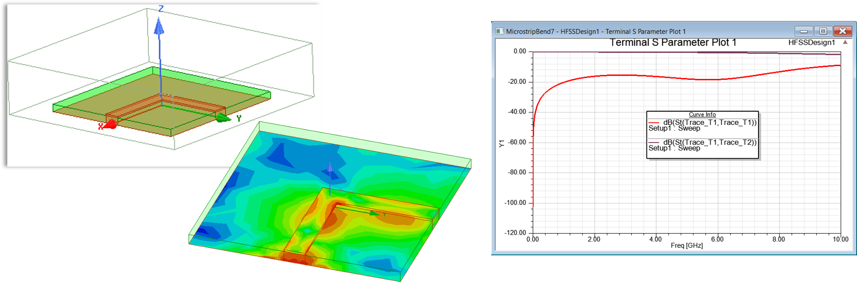
This workshop demonstrates creating parameterized HFSS geometry from scratch. The geometry created is a microstrip transmission line with a right-angle bend.
Workshop 5.2 — WR 90 Waveguide Filter Geometry Construction 
This workshop demonstrates creating parameterized geometry for a WR 90 X-band waveguide.
Workshop 5.3 — Assigning a Finite Conductivity Boundary to Band Pass Filter 
This workshop changes the default PEC boundary on a band pass filter example to a finite conductivity with aluminum properties.
Module 6: HFSS Lumped and Wave Port Basics
Workshop 6.1 — Microstrip Bend Lumped Ports Simulation 
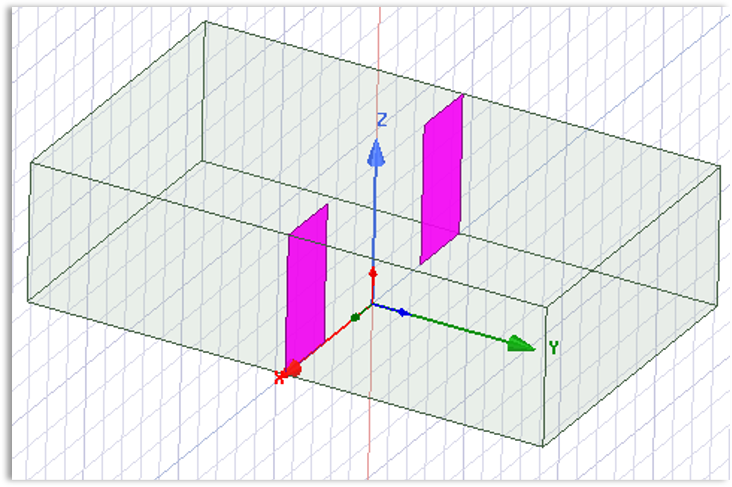
This workshop starts with a microstrip transmission line with a right-angle bend built in the geometry and demonstrates creating lumped ports along with calculating the resulting S-parameters.
Workshop 6.2 — Waveguide Wave Ports Simulation 
This workshop demonstrates exciting a wave guide with wave ports and post processing the results.
Module 7: Optimetrics and High-Performance Computing (HPC)
Workshop 7.1 — Microstrip Bend Parameter Sweep 
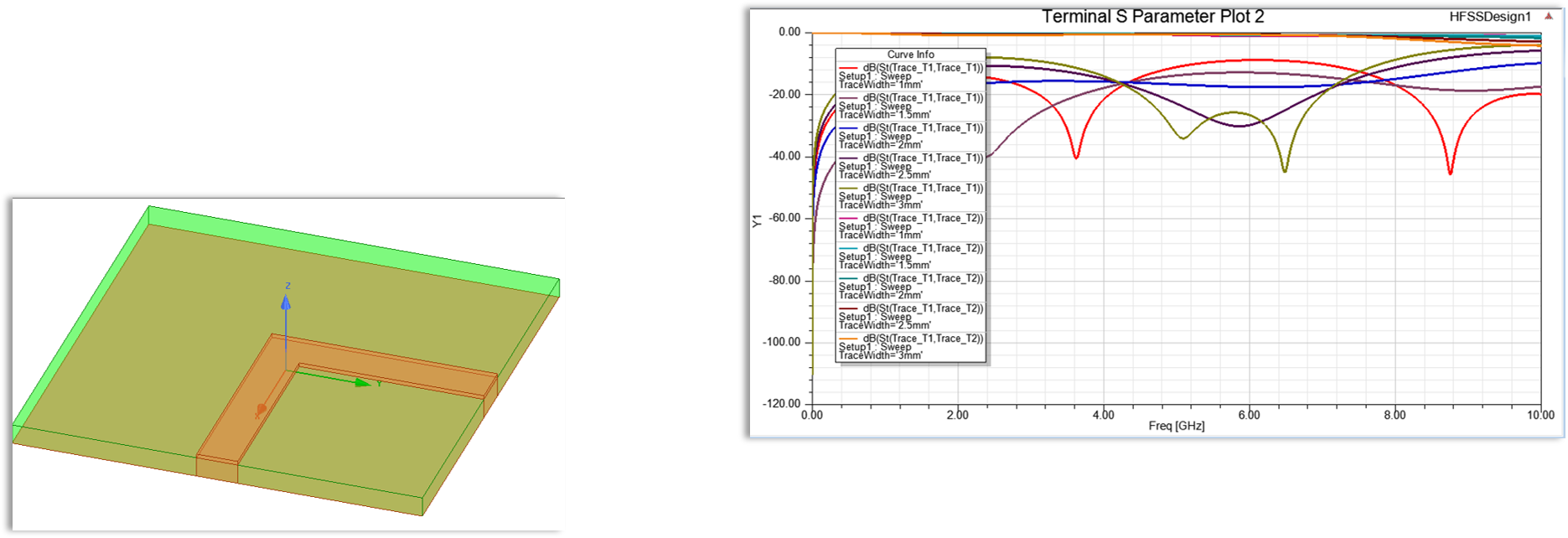
This workshop demonstrates a parameter sweep and tuning exercise on a microstrip bend.
Workshop 8.1 — 30mm Coax Construction and Simulation 
This workshop is an unscripted exercise to practice HFSS concepts with no detailed instructions. Only a general outline of the problem is provided.
Course Enrollment and Schedule
Introduction to Ansys HFSS
by Mai Vang | Jun 27, 2023
This 1-day course provides an introduction to modeling motors using Ansys RMxprt and Ansys Maxwell.
During the course, students will build hands-on skills by setting up and solving a variety of simulation models during the workshop sections.
Prerequisites for this course are DRD’s Introduction to Maxwell course and practice gaining proficiency with Maxwell. DRD recommends that students who do not have those prerequisites delay attending this course until they attain them. This course does not assume any experience with RMxprt.
Section 1: Cogging Torque
Workshop 1 – Cogging Torque Calculation
This workshop will discuss how to use ANSYS Maxwell to calculate the cogging torque in an example 3-phase permanent magnet machine. Both a parametric static and pseudo-static transient methodology will be explored.
Section 2: Motor Power Balance
Workshop 2 – Motor Losses
This workshop explores an example induction motor to understand power loss prediction in Maxwell. It will show how to obtain these quantities during postprocessing, how to validate them through checking the power balance, and how to improve simulation accuracy on these results. RMxprt will be used to both analyze the motor and to generate Maxwell 2D and 3D models of the design.
Section 3: Demagnetization
Workshop 3 – Demagnetization Due to Short Circuit
This workshop will discuss how to use Ansys Maxwell to study the variation of Permanent Magnet Rotating Machine performances due to short circuit and related high value external fields and permanent magnets demagnetization.
Section 4: Machine Toolkit
Workshop 4 – Using the Machine Toolkit on a PMSM Model 
This workshop starts with an existing 3-phase permanent magnet synchronous machine model that’s set up to solve one operating point. The user will then use the Machine Toolkit extension to define the Design of Experiments runs which will populate the full operating space. Output maps such as efficiency, losses from different sources, torque vs. speed, and voltage/current in the d-q frame can be obtained for this design after running the DOE that the toolkit automatically creates.
Course Enrollment and Schedule
Ansys Maxwell Motor Modeling